


Open end
An end opening aligned with the housing arrangement.
Confirm the locating diameter and sealing surfaces.
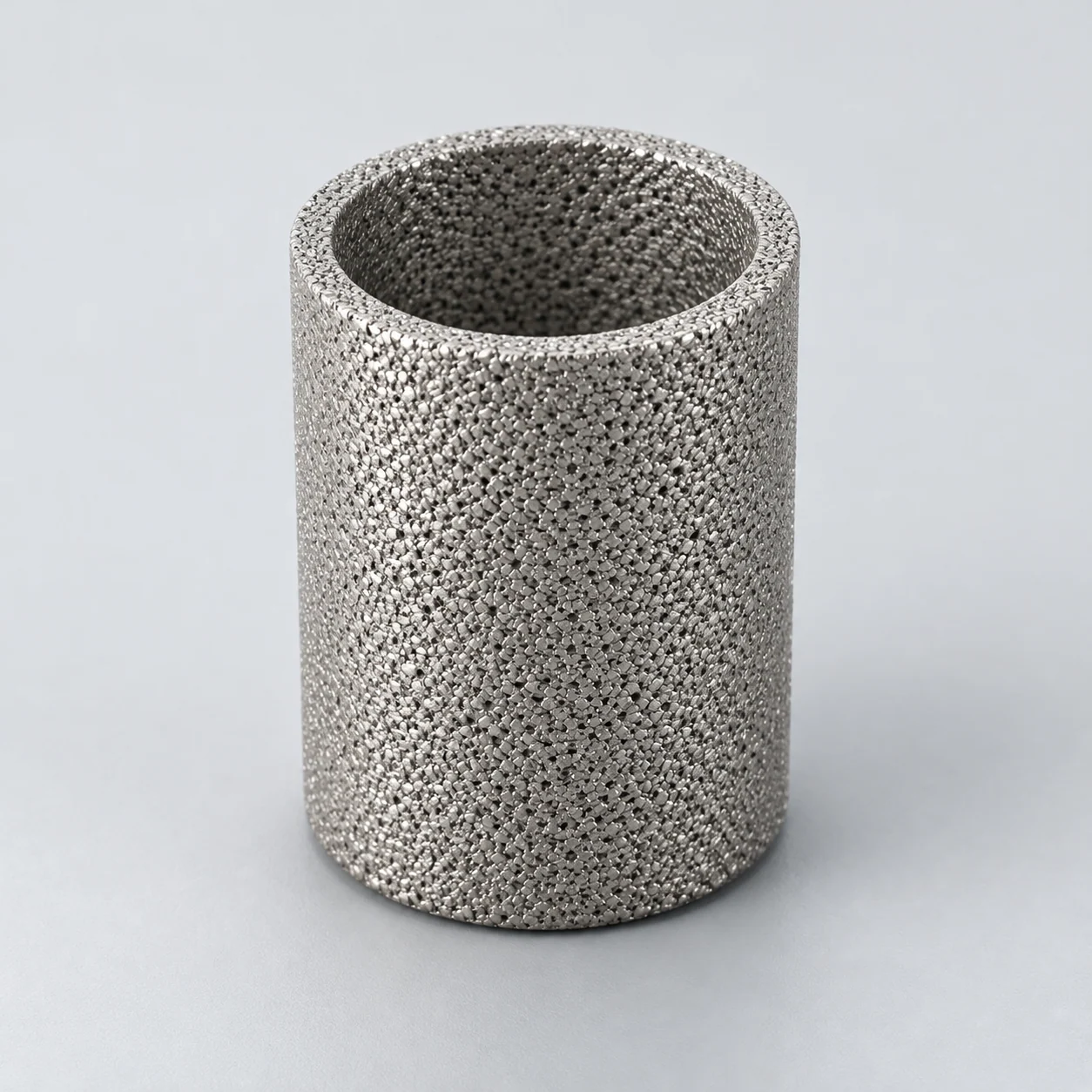
Explore a rigid porous structure made from bonded metal particles. Assess the required shape, wall thickness and flow path together with retention and maintenance needs.
Every element is made to order. Typical values are shown for orientation; dimensions, rating and materials are confirmed in the quotation drawing.
Sintered metal powder forms a porous wall through which the fluid passes. These cylindrical elements provide a different media structure from woven mesh or fiber felt. Match the end connection, pore grade and wall dimensions to the filtration duty.
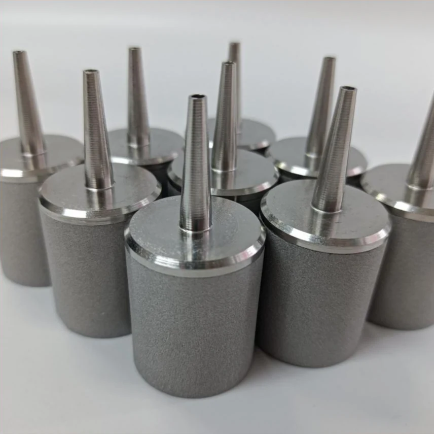
Confirm the selected dimensions, retention test and operating conditions before ordering. Ranges are not a single combined specification.
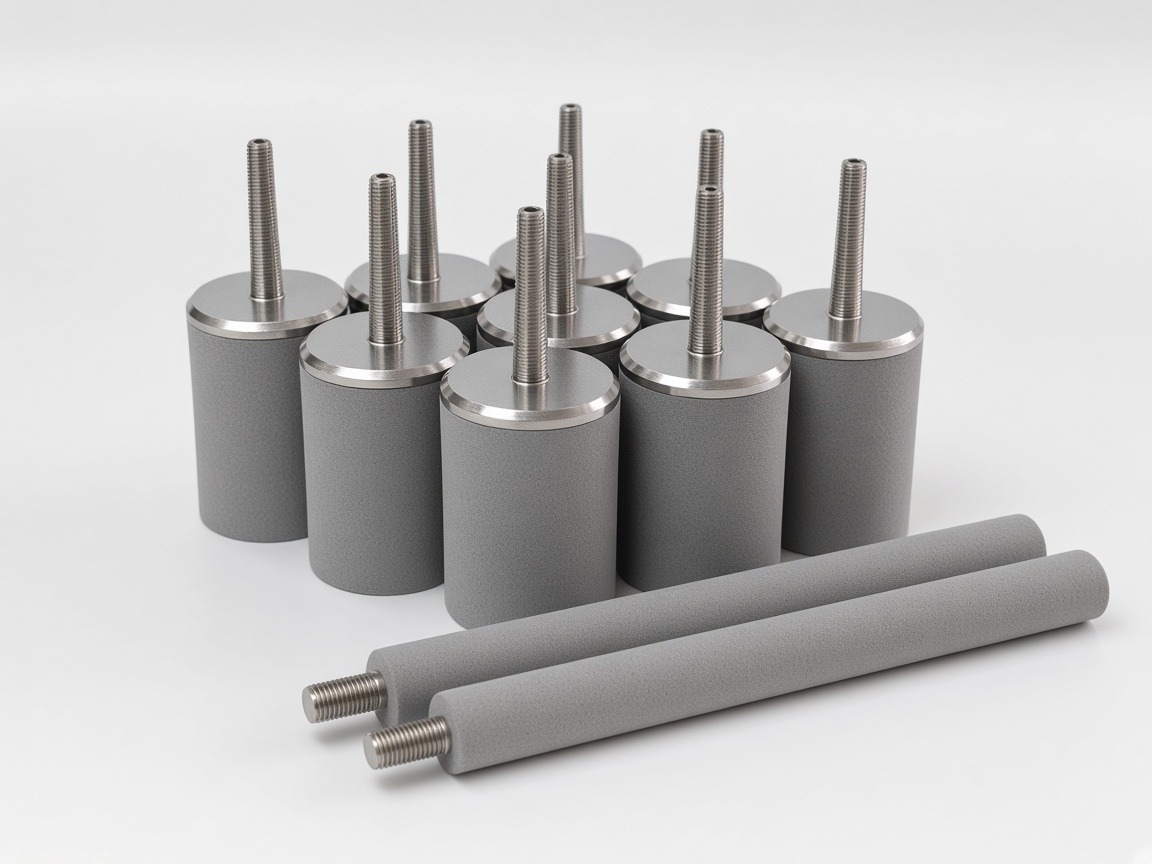
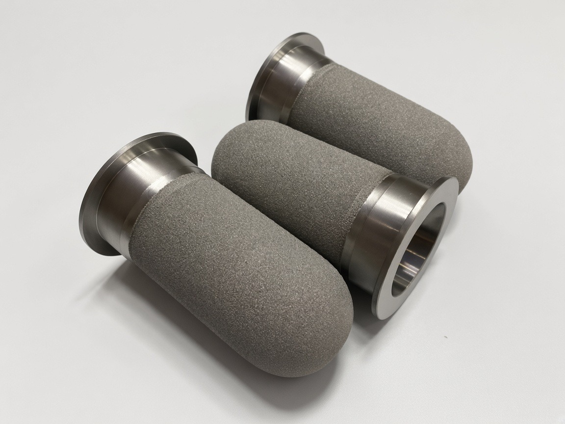
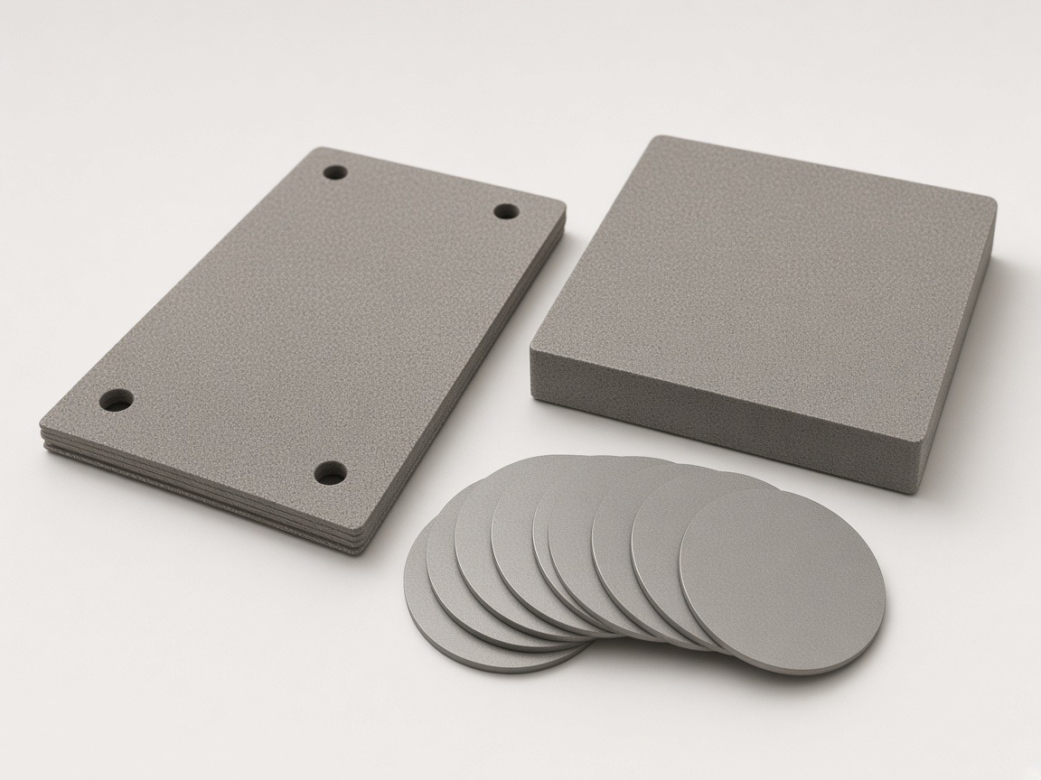
Start with the complete element and the task it must perform. You can discuss selection before every technical value is known.
This table lists the inputs needed from you. Element data are provided with the quotation; unknown input values can be left open.
Have only part of the information? Start with it; missing details can be clarified before a proposal.
These equipment guides cover different media, flow arrangements and acceptance questions. The shared powder-metal family does not establish that one element is interchangeable across these applications.
Review liquid chemistry and the assembled porous-titanium element before a separate downstream treatment stage.
On this page: batch-transfer dead-end recovery, with no reactor return shown. This differs from a reactor recirculation or crossflow loop.
Review gas chemistry, thermal cycling and the porous assembly before shortlisting a material.
On this page: a closed-end porous cup in a heated sample-branch housing. An inertial crossflow sampling tube uses a different flow arrangement; distinguish the bypass and sample flows.
On this page: open-ended crossflow tubes with a separate retentate outlet. This differs from a closed-end filter bank with a separate reverse-cleaning cycle.
Define solid-particle application and gas-flow conditions for the filter installed before a pressure regulator.
Start with the application and the tradeoffs. You can request help before every operating value is known.
Define the filtering area, support and sealing interface together. The drawings below describe geometry, not an approved manufacturing design.
A hollow cylindrical body with open ends.
Check wall thickness, active length and end connections.
A cup-shaped body with one closed end.
Identify which surfaces are porous and where the part seals.
A circular porous part for a defined installation.
Check thickness, diameter and the exposed working area.
Particle filtration, gas distribution and flow restriction need different acceptance tests. A component described as porous is not automatically qualified for all three functions.
Record the new element response before service and repeat the agreed checks after cleaning. Compare like-for-like conditions to distinguish remaining contamination from damage.
Some contaminants penetrate the porous network. Evaluate whether the cleaning fluid can reach and remove them without attacking the medium, fittings or seals.
An end opening aligned with the housing arrangement.
Confirm the locating diameter and sealing surfaces.
A thread-defined connection to the mating component.
Specify thread standard, size, engagement and seal.
A flange-defined mounting and sealing interface.
Provide bolt pattern, mating face and gasket details.
The table explains what to define for selection. It is a requirements worksheet, with product ratings and supply options still to be confirmed.
Scroll the table sideways to read all specification columns.
| Parameter / unit | What it means | What to specify |
|---|---|---|
| Porous body and fittingsalloy designation | A material name alone does not describe compatibility of the assembled part. | Complete process composition, impurities, cleaning fluid and required alloy identification. |
| Retention requirementµm + efficiency | Pore terminology, media grade designations and retention ratings are not automatically interchangeable. | Particle-removal target and agreed challenge or service acceptance test. |
| Permeability or flow curvem² or defined flow curve | A useful comparison keeps specimen geometry and test conditions consistent. | Flow versus differential pressure with fluid, temperature and test configuration. |
| Porous wall thicknessmm | Wall thickness is part of the flow path and mechanical design. | Inside and outside dimensions, tolerances and effective filtration area. |
| Operating flowm³/h or L/min | For gases, a standard-volume flow differs from the volume at the element. | Normal and peak flow; gas reference temperature and pressure where applicable. |
| Pressure and differential pressurebar or kPa | Line pressure and the pressure difference across the element describe different loads. | Upstream and downstream conditions, vacuum application and allowable forward/reverse differential pressure. |
| Temperature envelope°C | Process, start-up and cleaning temperatures may govern different parts of the assembly. | Continuous range, excursions and the temperature of each cleaning step. |
| Integrity test basisdefined test procedure | Test method, wetting liquid and assembly condition affect interpretation. | Agreed integrity method, baseline record and acceptance criteria. |
| Component form and connectionmm; drawing revision | Discs, closed-end cups and cylinders require different flow and sealing arrangements. | Dimensioned geometry, seal details, joints and installation clearance. |
A material name or micron value alone is not a complete specification. Pressure, temperature and cleaning limits apply to the assembled element.
A porous wall provides a distributed flow path. Thickness, pore geometry and open porosity must be considered together; equal grade names do not ensure equal hydraulic resistance. Compare measured permeability or pressure-loss data with the proposed wall geometry and fluid conditions.
A bubble-test result can support a pore-related quality check when the method and wetting conditions are defined. It is not a direct particle-removal rating. Keep the bubble-test requirement, particle-retention criterion and clean flow characteristic as separate acceptance items.
Solids retained near the surface may form a removable cake; particles trapped within the porous wall can be harder to release. Select the pore structure together with the particle distribution and cleaning sequence. Assess the initial filtrate and later cycles, rather than assuming that a finer grade always cleans better.
Sintered powder forms a connected pore network within a rigid body. A flat disc or plate needs an edge seal and a support arrangement suited to its span. A tubular element also needs defined end connections: the housing must separate feed from filtrate so the stream crosses the porous wall rather than bypassing it.
The same porous material can serve a different function when gas is distributed into liquid or transported through an electrode layer. Those applications do not establish a particle-filter rating or an interchangeable cartridge.
A model number is not a retention result. Ask for the particle size together with its measured efficiency, challenge material and test method; do not read a micron rating from the product code.
On a small screen, scroll the table sideways to see every column.
| Reported result | What it describes | What it does not establish |
|---|---|---|
| Particle size at an efficiency | 98% and 99.9% are different removal thresholds; each needs its associated size and method. | An unspecified absolute micron rating or a sterility claim. |
| Pressure-normalized air permeability | Flow divided by exposed area and test pressure, with the declared units. | Actual cartridge m³/h, liquid throughput or melt capacity. |
| Tubular external-pressure test | Resistance of the tested tube to the stated external load. | Allowable service differential pressure or reverse-pulse permission. |
| Alloy temperature description | A material/configuration statement under its stated exposure. | A common temperature limit for every alloy, joint, seal and finished element. |
A powder-sintered body contains connected passages between bonded particles. Particle size, compaction, sintering and wall geometry affect the resulting flow paths. A pore-size label or bulk porosity alone does not establish which particles the completed element retains at the required flow.
Prepare an acceptance specification for the actual tube, cup, disc or panel, including its joints and sealing interface. The fields below define the evidence to request; they are not confirmed ratings for a supplied element.
On a small screen, scroll the table sideways to see every column.
| Parameter | Unit or record | Required definition and evidence |
|---|---|---|
| Particle retention | µm; efficiency or beta ratio; test report | State nominal or absolute meaning, challenge particles, fluid, flow and acceptance criterion. A micron rating without the method is insufficient. |
| Pore and bubble-point assessment | Pa or kPa; wetting liquid; temperature | Identify the method, wetting procedure and tested area. Bubble pressure depends on the liquid and pore geometry; it is not an allowable operating pressure or proof of particle-retention efficiency. |
| Porosity and wall geometry | %; mm; controlled section drawing | Identify the measurement method, wall thickness, active area and any dense-to-porous transition. Porosity is not a pore-size distribution or a strength rating. |
| Permeability and clean resistance | Flow per unit area; differential pressure; fluid state | Record the test fluid, temperature and applied differential pressure. For gas, define actual or reference volume conditions. Compare equivalent wall thickness and area; media flow data does not directly equal assembled-element capacity. |
| Pressure and temperature envelope | MPa or bar; °C; forward/reverse direction | Separate line pressure from filtration differential pressure and reverse-cleaning load. Request direction-specific assembly evidence at the operating temperature, including the porous wall, joints, end fittings and seals. |
| Connection, integrity and repeat cleaning | Drawing revision; material record; test and cleaning procedure | Define end closure, threads or flange details, sealing faces and joint construction. Check for bypass at each joint and agree post-cleaning integrity and resistance criteria. |
Sintered titanium powder and titanium-fiber felt are different porous structures. A powder element is formed from bonded particles; a fiber medium is formed from bonded filaments and may include supporting layers. A shared titanium name does not make their thickness, permeability, retention or mechanical behavior interchangeable. Electrolyser porous-transport layers also have a different function from particle-filter elements.
Specify the exact metal grade and the evidence for the proposed construction. Material-purity statements or solid-metal corrosion data do not qualify an assembled porous element. Review the process fluid and cleaning exposure together, including temperature, concentration, contaminants and any relevant electrochemical conditions. A change to alloy, porosity, wall thickness or joining method requires a renewed assessment.
Structure determines how fluid travels through the medium and where particles are retained.

Metal powder particles are joined during sintering while connected voids remain between them. Fluid travels through these passages; powder size, processing and geometry influence the resulting medium.
Permeability characterizes flow through a porous material under defined conditions. Media flow data need the test fluid and geometry; a permeability value cannot be treated as the flow capacity of any finished cartridge.
A bubble test is useful for quality control of a wetted porous structure. It does not independently establish particle-removal efficiency or the complete pore-size distribution. A retention claim needs its own evidence.
Select an industry to see the process conditions and performance criteria used to specify this filter medium.
A formed porous part is a candidate where a rigid disc, cup or tube must fit a defined installation. Geometry does not merely set the envelope: the working wall and any narrow internal passage contribute to pressure loss. Define whether the component is intended to retain particles or deliberately restrict flow; those are different acceptance questions.
Check fit, clean flow and the relevant particle or flow-control result for the actual geometry.
A media grade does not establish the complete component’s pressure rating, instrument approval or service life.
A porous wall can retain catalyst while filtrate passes through it. Dead-end operation allows a cake to accumulate; recirculating or crossflow arrangements change transport along the surface and can change that buildup. The mode belongs to the system design. It cannot be inferred from a powder-element photograph or selected only by micron rating.
Compare initial and composite filtrate quality, pressure rise and repeatable cake discharge on representative feed.
Recovery yield, cycle time and catalyst activity must be evaluated in the actual process before a configuration is accepted.
Porous-metal process filtration can be evaluated for catalyst or activated-carbon removal during API manufacture. The important distinction is between a liquid-solid process step and a validated final sterile barrier. For a porous powder candidate, investigate whether the solids form a releasable cake or enter the wall; this affects quality during startup and cleaning recovery.
Use representative feed for feasibility work and review material, assembly and cleaning records required by the process owner.
Medical-device use is a separate OEM development task. Particle-retention test data alone do not establish sterility, biocompatibility or device suitability.
For gas sampling or process protection, a porous powder candidate can be evaluated against a defined solid-particle target. Deposits inside the wall can reduce permeability, so include loading and maintenance in the assessment. If liquid droplets or condensable vapor are present, assess phase changes and any separate separation stage instead of treating all contamination as particles.
Assess particle removal, pressure loss and maintenance under representative flow and contamination conditions.
This does not establish liquid coalescence, vapor removal, hazardous-gas qualification or an approved mechanical limit.
Titanium powder grades are listed separately from stainless-steel grades. Plate and disc configurations need their own span and support review; see the linked reference tables.
On a small screen, scroll the table sideways to see every column.
| Model | Rating at 98 %, µm | Rating at 99.9 %, µm | Air permeability, m³/(m²·h·kPa), ≥ | External compressive strength, MPa, ≥ |
|---|---|---|---|---|
| YS-SP-001 | 1 | 5 | 8 | 3.0 |
| YS-SP-003 | 3 | — | 12 | 3.0 |
| YS-SP-005 | 5 | 7 | 18 | 3.0 |
| YS-SP-007 | 7 | 10 | 40 | 3.0 |
| YS-SP-010 | 10 | 15 | 80 | 3.0 |
| YS-SP-015 | 15 | 20 | 160 | 3.0 |
| YS-SP-020 | 20 | 30 | 380 | 3.0 |
| YS-SP-030 | 30 | 45 | 550 | 2.5 |
| YS-SP-045 | 45 | 65 | 700 | 2.0 |
| YS-SP-065 | 65 | 85 | 1100 | 2.0 |
Rating at 98 % / 99.9 %: particle size retained in liquid at that efficiency. Compressive strength is an external-pressure (collapse) test value of tubular elements, not a working differential pressure; larger diameters and thinner walls give lower values. Porosity approx. 18–50 % depending on grade and forming method. “—” = not published, confirmed per order.
Reference values only; final specifications are confirmed for each custom order.
On a small screen, scroll the table sideways to see every column.
| Material (model) | OD, mm | Length, mm | Rating range, µm | Max. media temperature (oxidizing / inert) | Max. working ΔP, MPa (reference) |
|---|---|---|---|---|---|
| 316L (YS-SP) | 10–200 | 50–1500 (longer by welding) | 0.5–65 | 400 °C / 600 °C | 0.6 |
| Titanium Gr1 (YS-TI) | 14–150 | 20–1500 | 0.22–60 | 280 °C / — | 0.6 |
| Alloy 600 (YS-NA-600) | 20–200 | 20–1500 | 5 / 10 / 20 / 40 | 800 °C / by project | 0.6 |
| Alloy 400 (YS-NA-400) | 20–200 | 20–1000 | 5 / 10 / 20 / 40 | 500 °C / 600 °C | 0.6 |
| Alloy C-276 (YS-NA-276) | 20–100 | 20–1000 | 5–40 | by project | by project |
| Bronze (YS-BR) | by design | by design | 0.5–120 | by project | by project |
Standard 316L OD: 20, 25, 30, 40, 50, 60, 70, 80, 90, 100, 140 mm. End fittings: thread, flange, socket, quick-connect, welded caps. Temperatures are limits of the porous material; assembled elements are limited by seals and joints. Working ΔP is not the same as the external-pressure (collapse) strength.
Reference values only; final specifications are confirmed for each custom order.
On a small screen, scroll the table sideways to see every column.
| Model | Grade designation | Rating at 98 %, µm | Bubble point, Pa | Air permeability, m³/(m²·h·kPa), ≥ | Porosity, % |
|---|---|---|---|---|---|
| YS-SPM-0.1 | 0.1 | 1 | 45000 | 10 | 37 |
| YS-SPM-0.5 | 0.5 | 2 | 12800 | 60 | 37 |
| YS-SPM-1 | 1 | 3.2 | 10500 | 75 | 37 |
| YS-SPM-3 | 3 | 8.3 | 6000 | 120 | 37 |
Fine separation layer on a coarser 316L support. The grade designation is not a retention rating — use the 98 % column. External-pressure (collapse) strength ≥ 3.0 MPa (reference; not a working ΔP). OD 20–140 mm; L 100–1500 mm.
Reference values only; final specifications are confirmed for each custom order.
On a small screen, scroll the table sideways to see every column.
| Model | OD, mm | Length, mm | Nominal grade, µm | Material |
|---|---|---|---|---|
| YS-SPT | 8 / 10 / 13 / 19 / 25 | 50–1000 | 0.1–5 | 316L |
Nominal grade; retention efficiency is confirmed per order.
Reference values only; final specifications are confirmed for each custom order.
Keep the porous-wall description distinct from the finished element's required filtration result and acceptance evidence.
Distinguish a pore-related measurement from particle retention before choosing the required test and acceptance criterion.
Compare wall geometry and active area using flow and pressure-drop data for the stated fluid and temperature.
Define the wetting liquid, test method and assembly condition; a bubble-point value alone does not establish filtration performance.
No. Powder size describes a starting material; the connected pore structure after processing and a suitable retention test determine how the finished medium performs.
Interpret the result against the agreed method and baseline. Wetting liquid, temperature, incomplete wetting or a different test setup can change the result; investigate the cause before concluding that the element is damaged.
The form may look similar, but the application is different. A filter needs a particle-removal specification; a sparger needs gas-distribution performance in the intended liquid and geometry.
Describe the intended function and share any available section drawing. These inputs support a technical review and are optional at the first inquiry.
Inquiry contextSintered metal powder filter elements
Useful if available — optional for your first inquiry:
Use the full inquiry form to attach a drawing or file. The short form alongside accepts your message.
Your reference is:
Thank you. Your enquiry has been received.