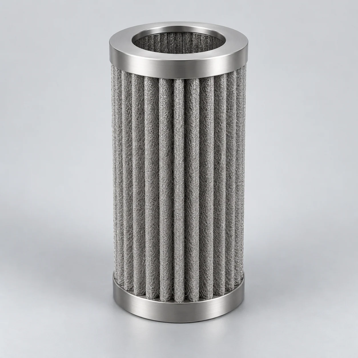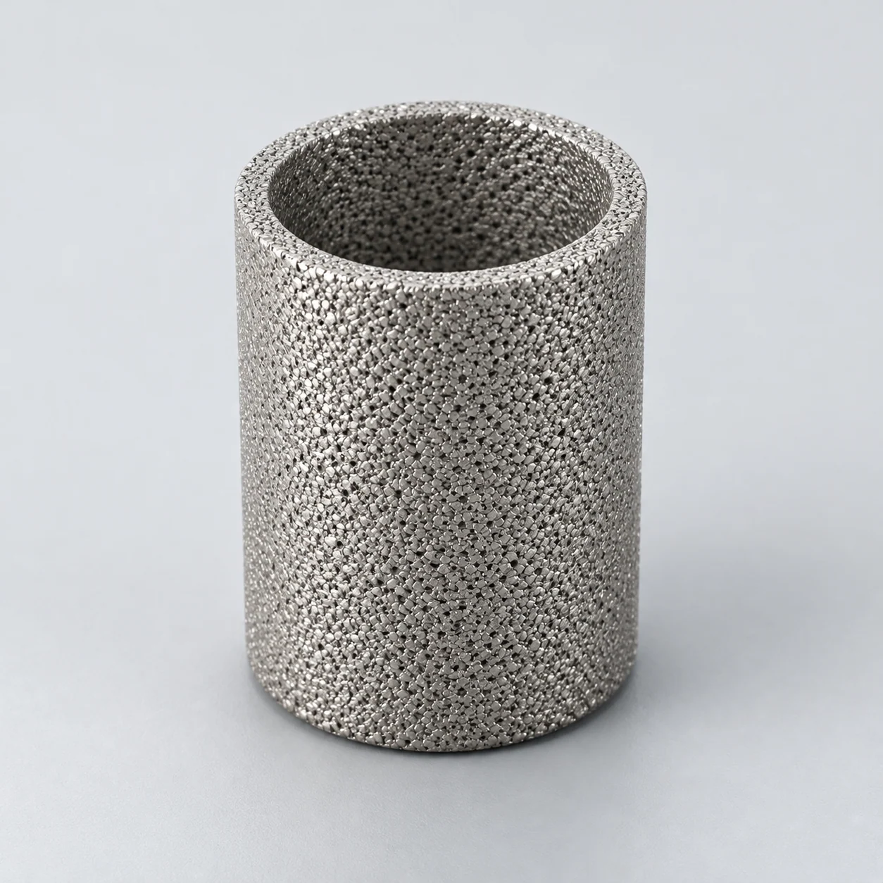
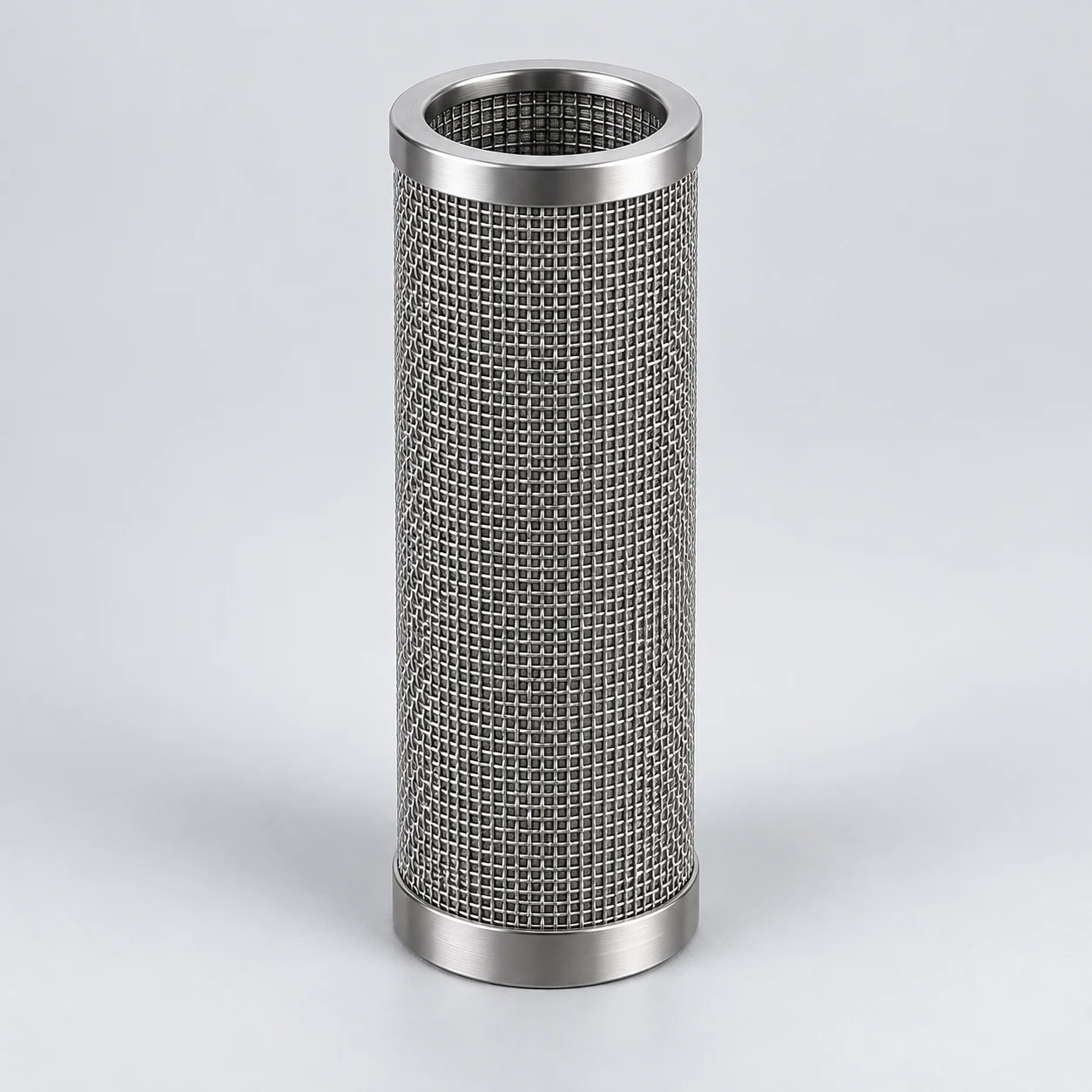


Extrusion or fiber-spinning line: polymer-melt candle filter
Element positionIn a heated melt-filter housing before a specified downstream operation such as an extrusion die or spinning assembly; the exact order of pump, filter and other components is equipment-specific.
How the element works
The melt passes through supported metal media while contaminants are retained. Mesh provides a surface-screening route for defined hard particles; fiber media provide a depth-capture route that must be evaluated for the actual contamination. Candle geometry increases installed area, but flow distribution and support determine how much of that area is useful.
Heated polymer-melt candle housing
Blue arrows illustrate an outside-in candle arrangement: melt enters the surrounding chamber, crosses the supported metal media and travels along the inner passages to the outlet. Dots on the dirty side indicate contamination. The outer border represents a heating jacket, not a second product-flow channel. The flow direction shown must be checked against the housing drawing.

- Melt inlet
The polymer stream enters the chamber around the candles. Pump position and thermal conditioning belong to the process design.
- Supported metal candle bank
Particles meet the porous media before the melt reaches the inner passages. The diagram does not equate surface mesh and depth-type fiber media.
- Clean collection and outlet
Inner passages open into a separate collection chamber. Connections, seals and support prevent a route around the media.
- Heating jacket
A conceptual thermal-control envelope surrounds the housing. Heating-medium piping and temperature-control design are omitted.
Typical operating conditions
- Polymer grade, temperature and shear-dependent viscosity influence resistance and processing behavior.
- Hard particles, degraded polymer and deformable contamination may require different evaluation methods.
- Heat-up, shutdown and cleaning impose thermal and mechanical conditions beyond steady production.
Selection decisions
- Relate retention to quality
- Define the defects to control and how they will be measured in melt or finished product. Do not infer gel removal from a family name or pore measurement.
- Review hydraulics and geometry
- Assess throughput, viscosity, usable media area, pleat spacing and support against clean and terminal differential pressure, including the permitted flow direction.
- Plan thermal exposure
- Review temperature uniformity, residence-time concerns, seals and the proposed cleaning procedure with the equipment owner; verify element condition before reuse.
Verification and application limits
What to verify
Evaluate the proposed construction under representative melt conditions; track product defects, pressure-drop development and post-cleaning integrity using agreed acceptance criteria.
Application limits
Gel-removal efficiency, pressure tolerance and service life depend on the media grade, support and actual process, and require configuration-specific verification.