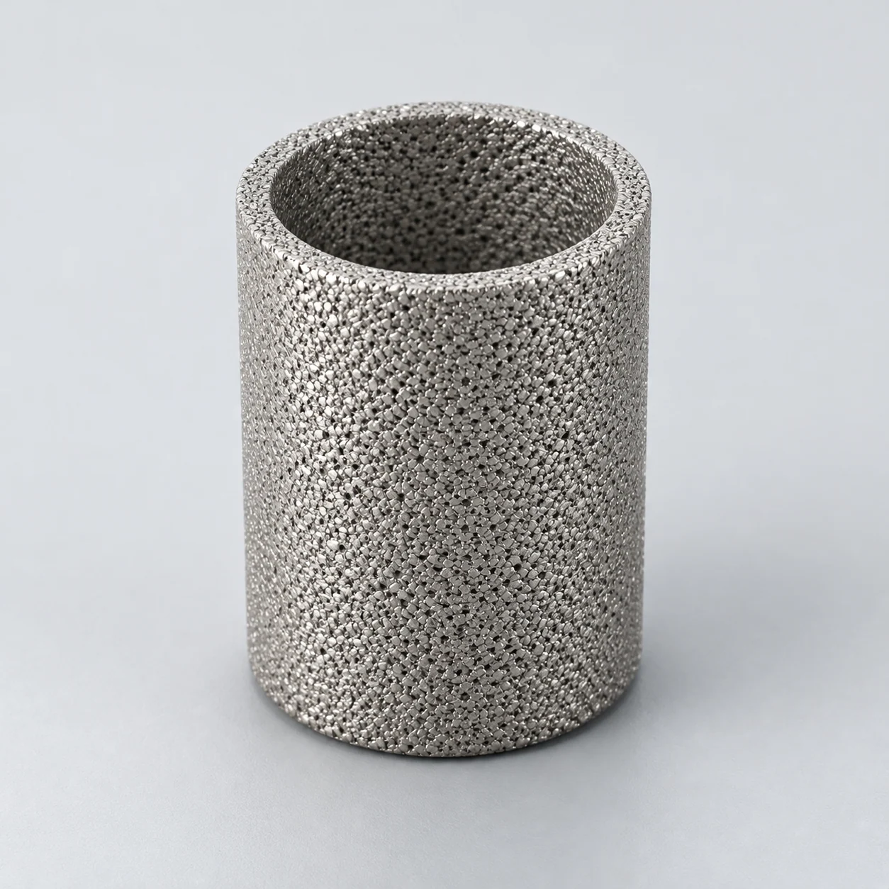
Specialist application guidance. Material, construction, temperature, emissions and service-life capability require separate component and project evidence before an offered product is approved.
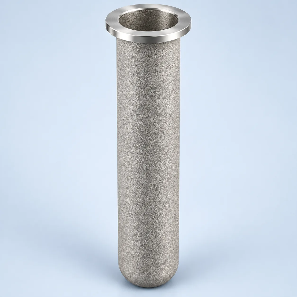
Closed-end hot-gas candle — section

- Filtering wall
A generic porous hot-gas wall is shown. Alloy, porous structure, joints and thermal-cycle acceptance require element-specific confirmation.
- Connection and seal
The open mounting end seals each bore to the clean-gas plenum and prevents dirty gas bypass around the wall.
- Clean central passage
Filtered hot gas enters the bore through the wall and rises into the clean-gas plenum in this selected outside-in layout.
- Closed lower end
The lower end is closed in the illustrated candle. Dust-bearing gas must cross the porous wall; reverse-pulse cleaning is a separate operating state.
Hot-gas vessel — outside-in filtration
The selected outside-in arrangement suspends closed-end candles below a sealed tube sheet. Gas passes from the dusty vessel through each porous wall into its bore and upward to the clean plenum. Dust collects outside the elements and falls toward the hopper during an appropriate cleaning cycle. Reverse-pulse cleaning is not shown.

The selected outside-in arrangement suspends closed-end candles below a sealed tube sheet. Gas passes from the dusty vessel through each porous wall into its bore and upward to the clean plenum. Dust collects outside the elements and falls toward the hopper during an appropriate cleaning cycle. Reverse-pulse cleaning is not shown.
- Dirty-gas vessel and hopper
Dust-bearing gas reaches the outside of the candles. Solids discharge is separate from the clean-gas outlet.
- Tube sheet and mounting seals
The separation plate and seals prevent dirty gas from bypassing the element walls.
- Closed-end porous candles
The closed lower end forces the illustrated gas path through the porous wall. Material and thermal cycling need assembly-specific evidence.
- Clean-gas plenum
Open bores communicate with the clean chamber and outlet; no reverse pulse is drawn in this filtration state.
Product images
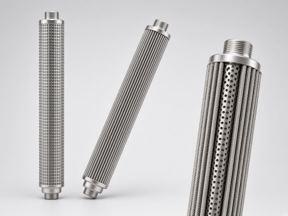
Elements between the dirty-gas vessel and clean plenum
A hot-gas vessel downstream of a calciner can use elements mounted in a separation plate between the dirty-gas space and clean-gas plenum. In a designed outside-in arrangement, dust collects on the outer surface while gas passes through the wall and exits through the open end. Dislodged dust falls toward a hopper; adequate spacing, gas distribution and solids discharge belong to the vessel design.
A pulse-cleaning system briefly reverses flow to release deposited cake. Its effect depends on cake cohesion, pulse conditions, element support and thermal gradients. A high maximum material temperature alone says little about pulse fatigue, differential-pressure resistance or performance after repeated start-ups.
- Confirm element location, flow direction and tube-sheet seal on the drawing.
- Review access for replacement and allowance for thermal movement.
- Define gas conditions during start-up, normal operation and shutdown.
Six inputs that determine the technical route
Size the system from actual hot-gas volume and a justified filtration velocity, then evaluate dust cake and cleaning. A reference to normal cubic metres must name its reference conditions. Keep element limits separate from vessel pressure and the compressed-gas supply pressure.
On a small screen, scroll the table sideways to see every column.
| Parameter | Unit or definition | Engineering question | Required input |
|---|---|---|---|
| Temperature history | °C, duration and rate of change | Continuous, transient and thermal-shock application | Normal/upset/start-up/shutdown profiles |
| Gas chemistry | Composition, moisture and impurities | Oxidation, corrosion and dew-point risk | O₂, reducing species, sulfur, halides and condensables |
| Dust properties | g/m³ actual; particle distribution | Cake formation, abrasion and discharge | Loading, stickiness, size and process variation |
| Flow and area | Actual m³/h; m²; m/min | Gas distribution and filtration velocity | Flow basis and effective element area |
| Pressure cycling | Forward/reverse ΔP, bar, at °C | Wall, seal and mounting stresses | Operating loss, alarm and pulse conditions |
| Acceptance | Test method, outlet dust and duration | Prove the required system result | Sampling basis and post-cycle inspection |
Two distinct material identities
FeAl describes an iron-aluminium intermetallic route; FeCrAl denotes an iron-chromium-aluminium alloy family.
Temperature application and construction limits
State continuous operating temperature, start-up peaks and upset excursions in °C, with duration and frequency. Add gas chemistry, oxygen content, moisture, dust abrasion and the cleaning-gas temperature. Confirm allowable conditions for the porous wall, joints, end fittings and seals together. An alloy oxidation figure cannot serve as the operating limit of an assembled element.
FeAl is not FeCrAl
Composition, microstructure and product form must be identified before comparing them. Neither label alone qualifies a complete element for the stated operating temperature. Porous bodies, membrane layers, welds, end fittings and supports may impose different limits.
- Request exact composition and the proposed construction.
- Review pulse-gas temperature as well as process-gas temperature.
- Check condensation and deposits during cooldown, not only hot steady operation.
A representative trial before a performance promise
Request retention, pressure-loss and cleaning results using representative dust and gas conditions, including repeated cycles where required. Send a process diagram, gas and dust analyses, temperature history, flow basis and proposed maintenance access. Identify whether the objective is product recovery, downstream equipment protection or an emission limit, because each needs a different acceptance plan.
- Record unresolved atmosphere or thermal-shock questions.
- Do not convert one case study into a universal emissions guarantee.
Specification and acceptance checks
Review the porous alloy, joints, mounting and pulse conditions together. Element-specific temperature, retention and forward/reverse-load limits are confirmed for each project; a bulk-alloy temperature or vessel pressure cannot substitute for assembled-element evidence.
On a small screen, scroll the table sideways to see every column.
| Check | Specify | Acceptance record |
|---|---|---|
| Thermal application | Normal/upset temperatures and rates of change | Agreed thermal exposure profile |
| Gas and dust | Chemistry, moisture, loading and particle distribution | Representative process analysis |
| Mounting and pulse | Seal, supports and reverse load at temperature | Drawing and cyclic-load evidence |
| Acceptance | Outlet dust, operating resistance and cycle duration | Post-cycle inspection and agreed sampling method |
- Keep FeAl and FeCrAl as separate material identities.
- State actual-volume and normal-volume flow bases explicitly.
Typical specifications
The following felt-material and candle references supplement the other porous constructions discussed above. A material temperature limit does not establish an assembled candle rating or gas compatibility.
On a small screen, scroll the table sideways to see every column.
| Material (model) | Rating range, µm | Porosity, % | Thickness, mm | Max. continuous media temperature (oxidizing gas) |
|---|---|---|---|---|
| 316L (YS-MF) | 3–200 | 55–88 | 0.27–0.70 | ≤ 400 °C |
| 310S (YS-MF-H) | by design | by design | by design | ≤ 480 °C |
| FeCrAl (YS-MF-A) | by design | by design | by design | ≤ 800 °C |
| Titanium Gr1, Ti ≥ 99.5 % (YS-MF-T) | by design | 50–80 | 0.10–1.50 | ≤ 280 °C |
| Nickel N6 (YS-MF-N) | by design | 50–80 | 0.25–1.00 | by project |
| Ti / Ni composite, 2–9 layers (YS-MF-TC) | by design | by design | 1.0–2.0 | by material |
Ti and Ni felts: standard 600 × 600 mm, up to 1000 × 1000 mm. In non-oxidizing service higher limits may apply; confirmed per project. Limits apply to the felt; assembled elements are limited by their seals and joints.
Reference values only; final specifications are confirmed for each custom order.
On a small screen, scroll the table sideways to see every column.
| Form (model) | Typical dimensions | Rating, µm | Notes |
|---|---|---|---|
| Hot-gas candle / bag (YS-HG) | Ø 120–160 mm; L 1000–6000 mm (longer on request) | by design | Multilayer felt 0.7–1.2 mm; flange or thread; pulse-jet cleaning |
Inch-series cartridge lengths 10/20/30/40 in = 254/508/762/1016 mm; metric lengths on request.
Reference values only; final specifications are confirmed for each custom order.
Prepare the specification for this application
Use these guides to resolve the next selection questions for this element. Each covers a separate part of the specification.
Product family: Sintered metal powder filter elements
- Gas flow basis for sizing sintered metal gas filters
Convert reference gas flow to the conditions at the hot filter element.
- Sintered filter material selection: 316L, titanium and special alloys
Distinguish FeAl, FeCrAl and other candidates before reviewing the assembly.
- How to clean sintered metal filters safely
Assess dust release and cleaning loads without assuming unlimited pulse reuse.