Application selection guidance. Exact media, alloy, mechanical ratings, compliance and material availability need element-specific evidence and project acceptance.
Gas particulate element — section

- Filtering wall
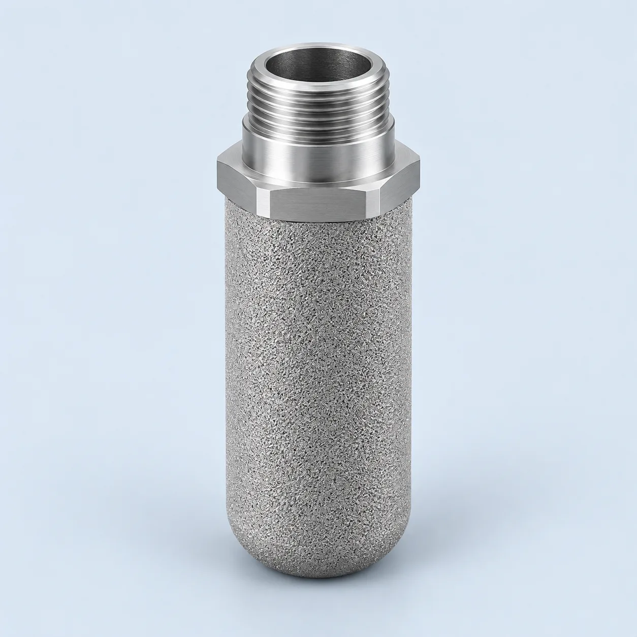
A porous particulate-filter wall is shown for process gas. Exact alloy, retention and mechanical limits require confirmation; aerosol coalescence is a separate application.
- Connection and seal
The connection seals the central passage to the filtered-gas outlet, preventing process gas from bypassing the porous wall.
- Clean central passage
In this selected outside-in layout, filtered process gas leaves through the bore toward the separate regulator or downstream component.
- Closed lower end
The illustrated closed end prevents axial entry of unfiltered gas. Confirm the element geometry and maintenance procedure against the housing drawing.
Gas particulate filter — upstream of a regulator
A dedicated particulate-filter housing sits upstream of a regulator in this selected arrangement. Gas surrounds the closed-end element, crosses its porous wall and leaves through the sealed central bore and clean chamber. The regulator is a separate component. A particle-filter drawing does not establish liquid-aerosol coalescence, gas drying or H₂S removal.

Gas particulate filter — upstream of a regulator. Numbered element positions and flow paths; explanations follow in the legend.
- Upstream gas housing
The separate housing receives gas containing solid particles before the regulator. Liquid carryover requires a separate assessment.
- Porous particulate element
The illustrated outside-in wall crossing retains specified solids. Exact alloy and retention must be verified for the offered element.
- Sealed clean connection
The clean bore passes through a sealed partition to the outlet; this barrier prevents an unfiltered short circuit.
- Pressure regulator
Pressure control is separate from particle filtration. Each component has its own operating and pressure limits.
Upstream of the regulator or instrument branch
A particulate element can be installed in a dedicated housing upstream of a pressure regulator, control valve or instrument branch to intercept solids that might foul small passages. The project drawing should distinguish that housing from any separate separator, coalescer, heater and pressure-control device.
In a specified outside-in arrangement, contaminated gas surrounds the element, traverses the porous wall and leaves through a clean central passage. Direction is a construction requirement, not an assumption based on shape. Confirm the clean-side seal and the maximum permitted flow so the filter does not become an unexpected restriction during a peak demand or pressure change.
- Define the solid contamination source and downstream tolerance.
- State whether liquid carryover can reach this stage.
- Check the complete operating envelope, including start-up and low inlet pressure.
Six linked specification fields
The same normal-volume flow corresponds to different actual volumes as pressure and temperature change. Supply the gas composition and flow reference, then assess the available pressure-loss budget. Do not confuse the high static line pressure with the much smaller differential load acting across an element.
On a small screen, scroll the table sideways to see every column.
| Parameter | Unit or definition | Purpose | Required confirmation |
|---|---|---|---|
| Retention target | µm at defined efficiency and gas challenge | Protect the downstream component | Particle distribution and agreed test |
| Gas throughput | Actual m³/h; stated normal reference | Assess area and restriction | Composition, inlet pressure and temperature |
| Pressure conditions | Line bar; element differential bar | Separate vessel and element design | Clean loss, alarm and forward/reverse limits |
| Contaminants | Water, H₂S, CO₂, chlorides and solids | Review corrosion and separate liquid applications | Normal and upset composition |
| Material condition | Exact alloy and fabrication state | Assess project-specific acceptance | Certificates, joints and applicable requirements |
| Fit and sealing | mm, connections and seal specification | Prevent leakage and bypass | Housing drawing and installation inspection |
Gas chemistry and exact alloy specification
Specify the exact stainless, duplex or nickel-alloy grade only after defining the gas composition and possible liquid phase. Duplex 2205 and superduplex 2507 are distinct grades; neither name qualifies a porous component for sour service. Review material condition, fabrication and assembly requirements against the actual project specification.
Grade selection is not blanket sour-service approval
316L can be a candidate in compatible conditions. Duplex, superduplex or nickel alloys may be considered when the actual chemistry justifies them, but availability in the selected porous construction must be confirmed. The grades' general use in oil and gas does not establish qualification of a particular powder element, weld or end fitting.
If sour service is relevant, provide the complete environmental and material conditions for review, including water, H₂S/CO₂ partial pressures, pH, chlorides and temperature. The required project standard and acceptance evidence must be stated explicitly. A family name or material certificate alone cannot establish all service requirements.
- Keep the media, support, weld and seal identities visible.
- Do not substitute a general corrosion table for the project material review.
- Include cleaning agents in compatibility assessment.
Inspection and reuse criteria
Use a differential-pressure trend together with the equipment's service procedure to plan inspection. Reverse cleaning is acceptable only where the actual element and housing are designed for it. Verify seals, physical condition and the agreed cleanliness or integrity criterion after maintenance. Send gas data, particle information, flow basis, housing drawing and service symptoms with the inquiry; include existing part dimensions when a replacement is required.
- Investigate wetting or condensate separately from dry-solids plugging.
- Record unresolved qualification points before requesting a final quotation.
Separate the gas-filter geometry from its service rating
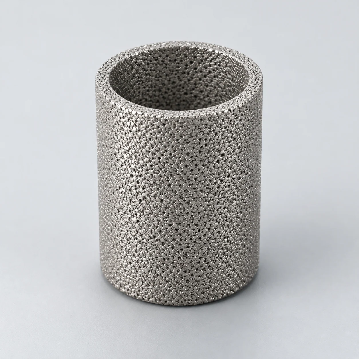
Pressed powder bodies can form cups, discs or tubes; the installed gas assembly determines which construction is appropriate. Review the porous wall, dense fitting and sealing path separately. A material coupon's strength or a room-temperature permeability value does not qualify an element for a specified gas composition and pressure cycle.
Treat a model identifier, a bubble-point result and particle-removal efficiency as different information. Confirm the efficiency at a stated particle size and flow before accepting a replacement.
On a small screen, scroll the table sideways to see every column.
| Decision | Inputs to provide | Evidence to request |
|---|---|---|
| Geometry and orientation | Existing element drawing, flow direction and sealing dimensions. | Controlled section and assembly leak check. |
| Gas flow | Composition, temperature, pressure and actual/reference volume basis. | Pressure-loss curve on the same gas-state basis. |
| Mechanical loading | Forward pressure loss, reverse exposure and pressure/temperature cycles. | Direction-specific element and joint qualification. |
| Reuse | Deposits, permitted cleaning medium and maintenance threshold. | Retention, leak and clean-flow checks after the agreed cycles. |
- Keep solid-particle retention separate from liquid coalescence and gas-phase contaminant removal.
Specification and acceptance checks
Separate solid-particle protection from liquid-aerosol and vapor-removal applications. Element-specific efficiency, flow and differential-pressure ratings are confirmed for each project; confirm gas conditions and the element/housing seal before selecting a replacement.
On a small screen, scroll the table sideways to see every column.
| Check | Specify | Acceptance record |
|---|---|---|
| Gas basis | Composition, pressure, temperature and flow reference | Actual-volume operating envelope |
| Contaminants | Particles, water, oil and relevant corrosive species | Separate removal targets and methods |
| Pressure limits | Static line pressure and element differential pressure | Housing and element records at temperature |
| Fit and acceptance | Ends, seals, orientation and leak criterion | Controlled drawing and retention/leak tests |
- A solid-particle filter is not automatically a liquid coalescer.
- Qualify material and joint requirements for the specific gas composition.
Prepare the specification for this application
Use these guides to resolve the next selection questions for this element. Each covers a separate part of the specification.
Product family: Sintered metal powder filter elements
- Gas flow basis for sizing sintered metal gas filters
Specify gas flow, absolute pressure and temperature at the regulator-filter application.
- Sintered filter micron rating: what it does and does not tell you
Define solid-particle retention separately from liquid coalescence and dehydration.
- Sintered filter material selection: 316L, titanium and special alloys
Review gas chemistry and any wet-H₂S requirements for the exact assembly.