

Open end
An end opening aligned with the housing arrangement.
Confirm the locating diameter and sealing surfaces.
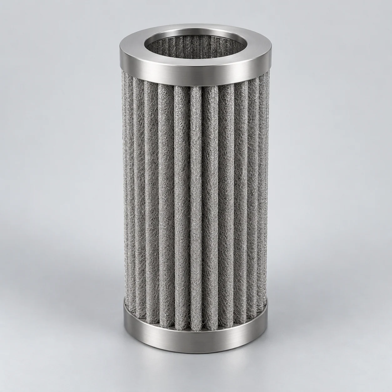
Explore a bonded network of metal fibers, including possible pleated constructions. Compare working area, support and loading behavior within the available installation envelope.
Every element is made to order. Typical values are shown for orientation; dimensions, rating and materials are confirmed in the quotation drawing.
Sintered metal fibers form a porous network that can be used as sheet media or formed into cylindrical filter elements. The media geometry and support structure determine how the available housing space is used. Review viscosity, solids loading and the cleaning cycle when selecting the media.
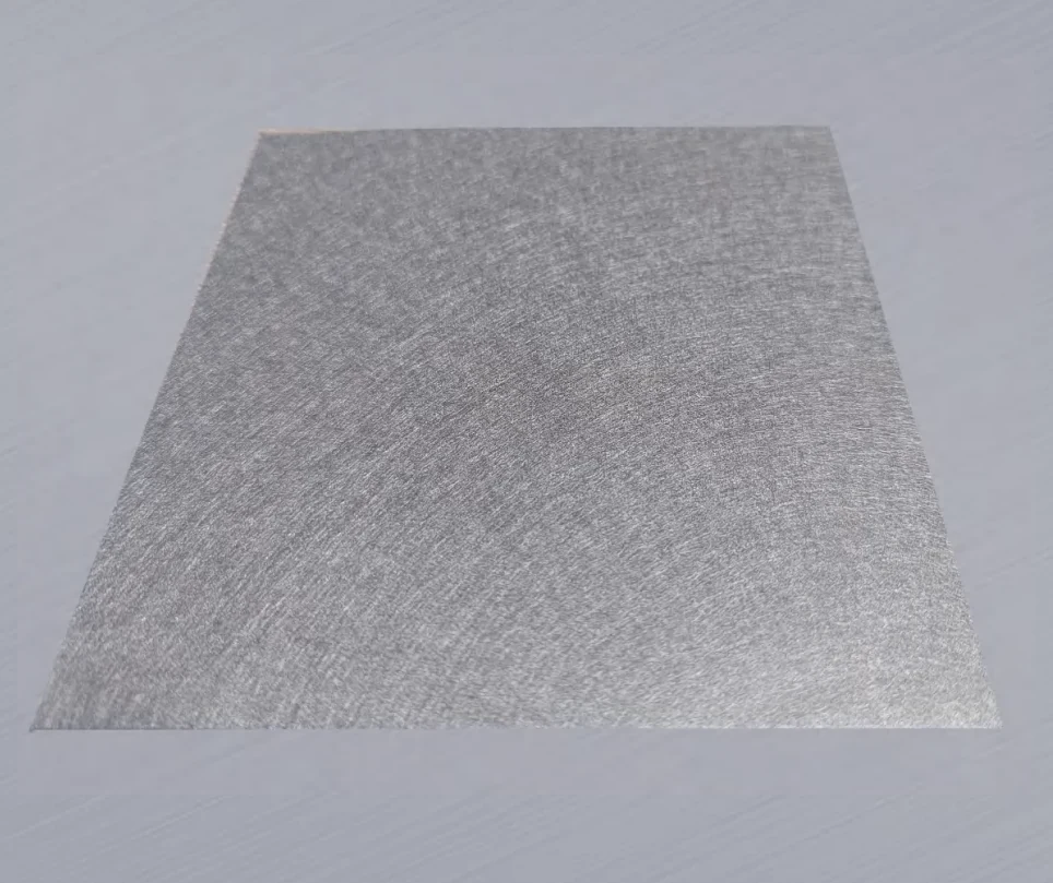
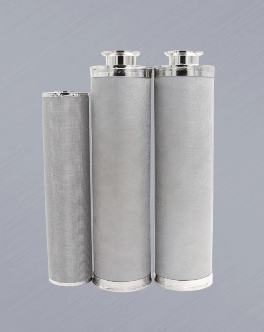
Confirm the selected dimensions, retention test and operating conditions before ordering. Ranges are not a single combined specification.
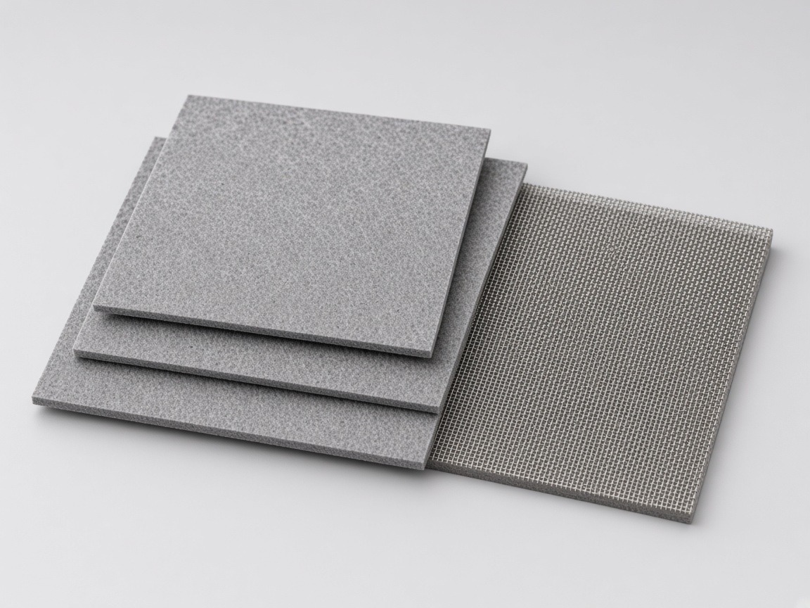
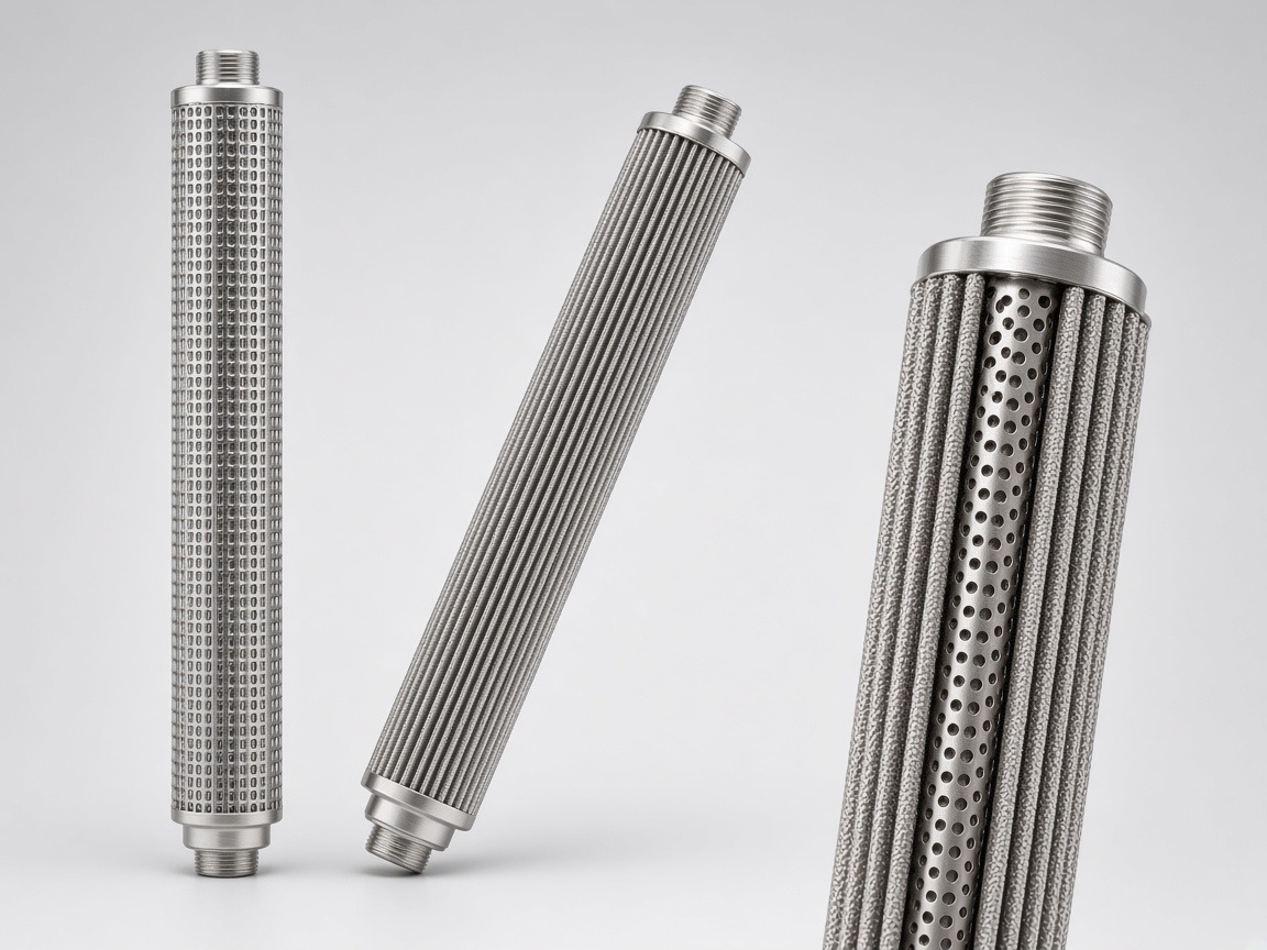
Start with the complete element and the task it must perform. You can discuss selection before every technical value is known.
This table lists the inputs needed from you. Element data are provided with the quotation; unknown input values can be left open.
Have only part of the information? Start with it; missing details can be clarified before a proposal.
Review a supported pleated-fiber candle in a melt-filter housing, with mesh retained as a separate candidate. For another application, describe the actual installation rather than treating this arrangement as universal.
Connect melt viscosity and allowable pressure loss to the pleat pack and heated candle housing.
Start with the application and the tradeoffs. You can request help before every operating value is known.
Define the filtering area, support and sealing interface together. The drawings below describe geometry, not an approved manufacturing design.
A cylindrical element using folded filtering media.
Confirm usable area, pleat spacing and support construction.
A tubular assembly with a defined filtering surface.
Confirm media support, seams and end construction.
A flat section for a specified component or assembly.
Define sheet dimensions, backing and the installation method.
Compare media under equivalent fluid conditions, then include supports and the assembled cartridge. High void fraction by itself does not establish a usable flow rating.
A compact pleat pack can increase nominal area while reducing access for viscous fluid or accumulated solids. Define the loading behavior before selecting the pleat arrangement.
After cleaning, low pressure drop alone is not proof of recovery: a damaged assembly can also pass more flow. Pair the hydraulic comparison with an agreed integrity assessment.
An end opening aligned with the housing arrangement.
Confirm the locating diameter and sealing surfaces.
A thread-defined connection to the mating component.
Specify thread standard, size, engagement and seal.
A flange-defined mounting and sealing interface.
Provide bolt pattern, mating face and gasket details.
The table explains what to define for selection. It is a requirements worksheet, with product ratings and supply options still to be confirmed.
Scroll the table sideways to read all specification columns.
| Parameter / unit | What it means | What to specify |
|---|---|---|
| Fiber and assembly materialsalloy designation | Compatibility must include fibers, support layers, welds and end fittings. | Process and cleaning exposure, required alloy and material records. |
| Retention performanceµm + efficiency | A micron rating does not describe the full performance of a layered fiber medium. | Particle distribution, required efficiency and the agreed test conditions. |
| Fiber-media structurelayer arrangement | Fiber diameter, thickness and layer sequence affect the available passages. | Media designation, upstream face and construction evidence. |
| Porosity and permeability%; defined flow test | Void fraction and flow behavior are related but are not the same measurement. | Comparable media data and a clean-element flow curve. |
| Effective media aream² | Developed pleat area may differ from the area that is hydraulically useful. | Pleat height, count, spacing, support details and envelope dimensions. |
| Flow and fluid propertiesm³/h; mPa·s | Viscosity and flow variation affect pressure loss and how the element loads. | Normal, peak and start-up conditions; gas flow reference basis where relevant. |
| Differential-pressure envelopekPa or bar | Forward filtration and reverse cleaning apply different mechanical loads. | Clean allowance, service endpoint and approved reverse-flow application. |
| Thermal cycle°C | The complete assembly must tolerate the intended operating and cleaning cycle. | Continuous temperature, peaks, duration and cooling or heating sequence. |
| Regeneration and reusedefined procedure | Cleanability must be demonstrated for the contaminant and element construction. | Foulant, proposed method, inspection criteria and post-cleaning baseline comparison. |
A material name or micron value alone is not a complete specification. Pressure, temperature and cleaning limits apply to the assembled element.
Fiber diameter, layer mass and layer sequence contribute to the porous network. A fiber diameter is not the retained particle size. Compare the intended surface- or depth-loading construction with a stated retention test and flow direction; do not infer a universal micron rating from one structural parameter.
Void fraction alone cannot specify permeability. Thickness, connected flow paths and the complete support arrangement also matter. Compare clean pressure loss at the same operating conditions, then track how captured solids change it. Research on pore modification illustrates that structure and resistance must be assessed together, not assigned by alloy name.
Pleating can fit more medium into an envelope, but tightly spaced folds and supports can restrict access or collect bridging deposits. Use an effective-area definition and the assembly’s measured flow behavior. Cleaning must reach the relevant deposits without imposing an unverified reverse load.
A micron rating needs a particle-size definition and a test efficiency. For an agreed particle threshold x, define βx = Nup(≥x) / Ndown(≥x), where upstream and downstream counts use the same particle-sizing and sample-volume basis. The corresponding removal efficiency is ηx = (1 − 1/βx) × 100%.
Calculation example only: if βx = 75, the arithmetic gives ηx ≈ 98.67% at that threshold. This is not a measured result for our media or elements, does not qualify a supplied micron rating and does not establish the same ratio at other particle sizes.
Sintered fiber felt combines bonded fibers into a porous network. Fiber diameter is a construction input, not a particle-retention rating. Agree both media properties and finished-element requirements.
On a small screen, scroll the table sideways to see every column.
| Parameter | How to specify and compare | Evidence to request |
|---|---|---|
| Particle retention | Distinguish average, nominal and absolute descriptions; state efficiency. | Challenge particles, test method and revision. |
| Thickness and structure | State thickness under specified load and support meshes. Bulk density is mass/bulk volume; porosity is void fraction. | Measurement conditions and layer specification. |
| Bubble point | Pressure at bubble onset: match wetting liquid and temperature; do not equate it with retention efficiency. | Test conditions and result. |
| Air permeability | Compare flow per exposed area at a stated specimen pressure difference. | Air-test pressure, temperature and specimen thickness. |
| Alloy and assembly | Specify alloy grade, seams, ends and seals; assess the complete element. | Material traceability, drawing and loading evidence. |
Reference air tests use 200 Pa for fiber felt and 1000 Pa for mesh. Confirm the specimen pressure difference before comparison; neither is an allowable operating differential pressure. Unit conversion: 1 L/(dm²·min) = 6 m³/(m²·h).
For viscous liquids or melts, request viscosity at operating temperature. Pleat height, spacing, support and blocked areas determine usable area; a flat-media air value cannot predict melt throughput.
Structure determines how fluid travels through the medium and where particles are retained.

Fine metal fibers are laid into a web and joined by sintering. Unlike woven mesh, the flow passages follow a three-dimensional network rather than a repeating woven pattern.
Fiber-media construction and operating mode influence whether particles accumulate within the medium or form a surface cake. Cleaning and capacity should therefore be assessed for the proposed application, not inferred from the word felt.
Pleating can increase media area inside a cartridge envelope. Spacing and support still matter: the flow must reach that area and the retained solids must have room to accumulate or be removed.
Select an industry to see the process conditions and performance criteria used to specify this filter medium.
A layered fiber medium may be considered when particle control and working area are important in a limited envelope. Depth loading stores contamination within the network, which affects the maintenance route. Cold-start viscosity can make a circuit hydraulically more demanding than the warm steady state; compare the element and its supports within the actual system.
Review clean and loaded hydraulic behavior with particle results, including the condition after intended cleaning.
No hydraulic-system equivalence, cold-start rating or guaranteed service interval is implied.
A fiber network can provide distributed capture through its thickness. In a polymer process, hard particles, agglomerates and deformable gels do not present the same challenge. Media layering and flow direction affect where material accumulates. More area can help the hydraulic question, but inaccessible folds or retained degraded polymer can undermine the intended operating benefit.
Assess melt quality and pressure rise together, followed by the intended offline cleaning and inspection.
Polymer names alone do not establish compatibility. Media benefits and reuse performance depend on the complete element and its operating conditions.
The intended loading mode matters more than the fiber label. A surface-oriented construction can be evaluated for collecting powder and releasing deposits; a depth-oriented construction retains material within the network. Define the process role before transferring either concept to a product-contact or utility stream, and assess contamination control and the cleaning route for that role.
Check retained-product or downstream quality, deposit release, material compatibility and post-cleaning condition.
This is not a sterile barrier or medical-device approval. Powder-handling hazards and OEM validation require their own assessments.
For a dry-particle gas service, a surface-oriented fiber construction may be evaluated with a cake-removal strategy. The cake changes both capture and pressure loss; its release depends on the deposits and the system, not just the medium. Gas composition and actual operating volume are needed to interpret a flow curve or scale an element area.
Review particle quality and pressure-loss recovery over representative filtration/cleaning cycles.
A metal fiber particle medium is not automatically a coalescer, flame arrestor or qualified hazardous-gas assembly.
On a small screen, scroll the table sideways to see every column.
| Model | Rating, µm | Bubble point, Pa | Air permeability at 200 Pa, L/(dm²·min), ≥ | Porosity, % | Thickness, mm | Dirt-holding capacity, mg/cm² |
|---|---|---|---|---|---|---|
| YS-MF-003 | 3 | 12000–12300 | 9 | 55–68 | 0.30–0.35 | 1–6 |
| YS-MF-005 | 5 | 6000–7600 | 30 | 70–78 | 0.34–0.40 | 2–6 |
| YS-MF-007 | 7 | ≈5000 | 55 | ≈72 | ≈0.27 | ≈6.5 |
| YS-MF-010 | 10 | 3500–3800 | 100 | 75–78 | 0.32–0.50 | 4–8 |
| YS-MF-015 | 15 | 2300–2600 | 130 | 78–82 | 0.37–0.68 | 8–11 |
| YS-MF-020 | 20 | 1700–2000 | 230 | 75–82 | 0.49–0.68 | 12–15 |
| YS-MF-025 | 25 | 1400–1560 | 320 | 79–80 | 0.60–0.68 | 15–19 |
| YS-MF-030 | 30 | 1100–1300 | 450 | 79–80 | 0.62–0.68 | 18–23 |
| YS-MF-040 | 40 | 900–1020 | 580 | 77–80 | 0.53–0.68 | 23–26 |
| YS-MF-060 | 60 | 630–800 | 1000 | 85–87 | 0.65–0.70 | 30–36 |
| YS-MF-080 | 80 | ≈700 | 1300 | ≈85 | ≈0.68 | ≈40 |
| YS-MF-100 | 100 | — | 1220 | ≈88 | — | — |
Bubble point: ISO 4003-type test; air permeability: ISO 4022-type test at 200 Pa; “—” = not published, confirmed per order. Variants: high dirt-holding (higher porosity), high-pressure (lower porosity, denser), and single- or double-side guard mesh. Standard sheet up to 1200 × 1500 mm.
Reference values only; final specifications are confirmed for each custom order.
On a small screen, scroll the table sideways to see every column.
| Material (model) | Rating range, µm | Porosity, % | Thickness, mm | Max. continuous media temperature (oxidizing gas) |
|---|---|---|---|---|
| 316L (YS-MF) | 3–200 | 55–88 | 0.27–0.70 | ≤ 400 °C |
| 310S (YS-MF-H) | by design | by design | by design | ≤ 480 °C |
| FeCrAl (YS-MF-A) | by design | by design | by design | ≤ 800 °C |
| Titanium Gr1, Ti ≥ 99.5 % (YS-MF-T) | by design | 50–80 | 0.10–1.50 | ≤ 280 °C |
| Nickel N6 (YS-MF-N) | by design | 50–80 | 0.25–1.00 | by project |
| Ti / Ni composite, 2–9 layers (YS-MF-TC) | by design | by design | 1.0–2.0 | by material |
Ti and Ni felts: standard 600 × 600 mm, up to 1000 × 1000 mm. In non-oxidizing service higher limits may apply; confirmed per project. Limits apply to the felt; assembled elements are limited by their seals and joints.
Reference values only; final specifications are confirmed for each custom order.
On a small screen, scroll the table sideways to see every column.
| Form (model) | Typical dimensions | Rating, µm | Notes |
|---|---|---|---|
| Pleated liquid cartridge (YS-MFE) | OD 35–80 mm; L 100–1500 mm | 1–100 | Perforated core and guard; thread, flange or 222/226 socket |
| Pleated melt candle (YS-PC) | by housing drawing | 3–100 | See polymer-melt page |
| Hot-gas candle / bag (YS-HG) | Ø 120–160 mm; L 1000–6000 mm (longer on request) | by design | Multilayer felt 0.7–1.2 mm; flange or thread; pulse-jet cleaning |
Inch-series cartridge lengths 10/20/30/40 in = 254/508/762/1016 mm; metric lengths on request.
Reference values only; final specifications are confirmed for each custom order.
Resolve media identity, usable area and maintenance before treating a pleated construction as a replacement.
Compare sintered metal-fiber media, woven metal mesh and sintered powder-metal media for the application, rather than by appearance or the presence of pleats.
Review viscosity, support blockage and accessible pleat area when assessing the complete element's pressure loss.
Check whether cleaning can reach retained contamination without damaging the fiber medium, support or end joints.
No. Fiber felt is a nonwoven network; mesh is woven from wires. The structures create different flow and loading behavior, so the media should be compared by application and test evidence.
No. Service life also depends on contaminant loading, usable area, flow distribution and the allowable pressure drop. The added area must remain accessible under actual process conditions.
No. The medium, pleats, supports, joints and cleaning system must be evaluated together for reverse-flow loading. Confirm the sequence and acceptance criteria for the specific assembly.
Share the installation envelope and filtration task. A complete set of performance data is not required to start the discussion.
Inquiry contextSintered metal fiber filter elements
Useful if available — optional for your first inquiry:
Use the full inquiry form to attach a drawing or file. The short form alongside accepts your message.
Your reference is:
Thank you. Your enquiry has been received.