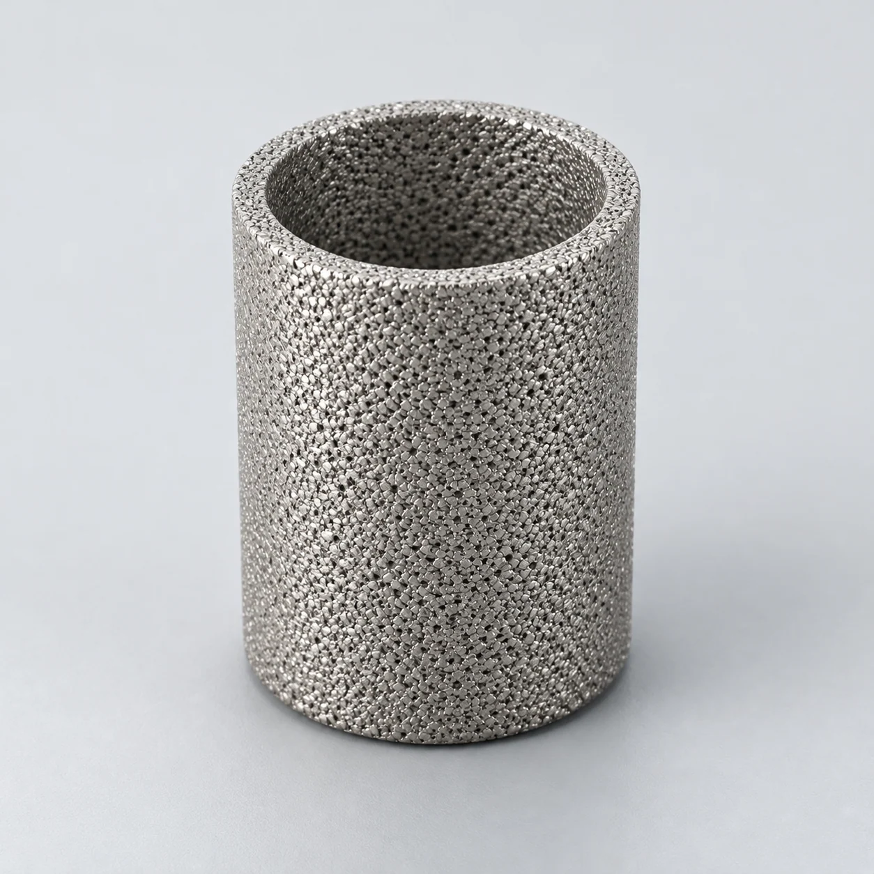
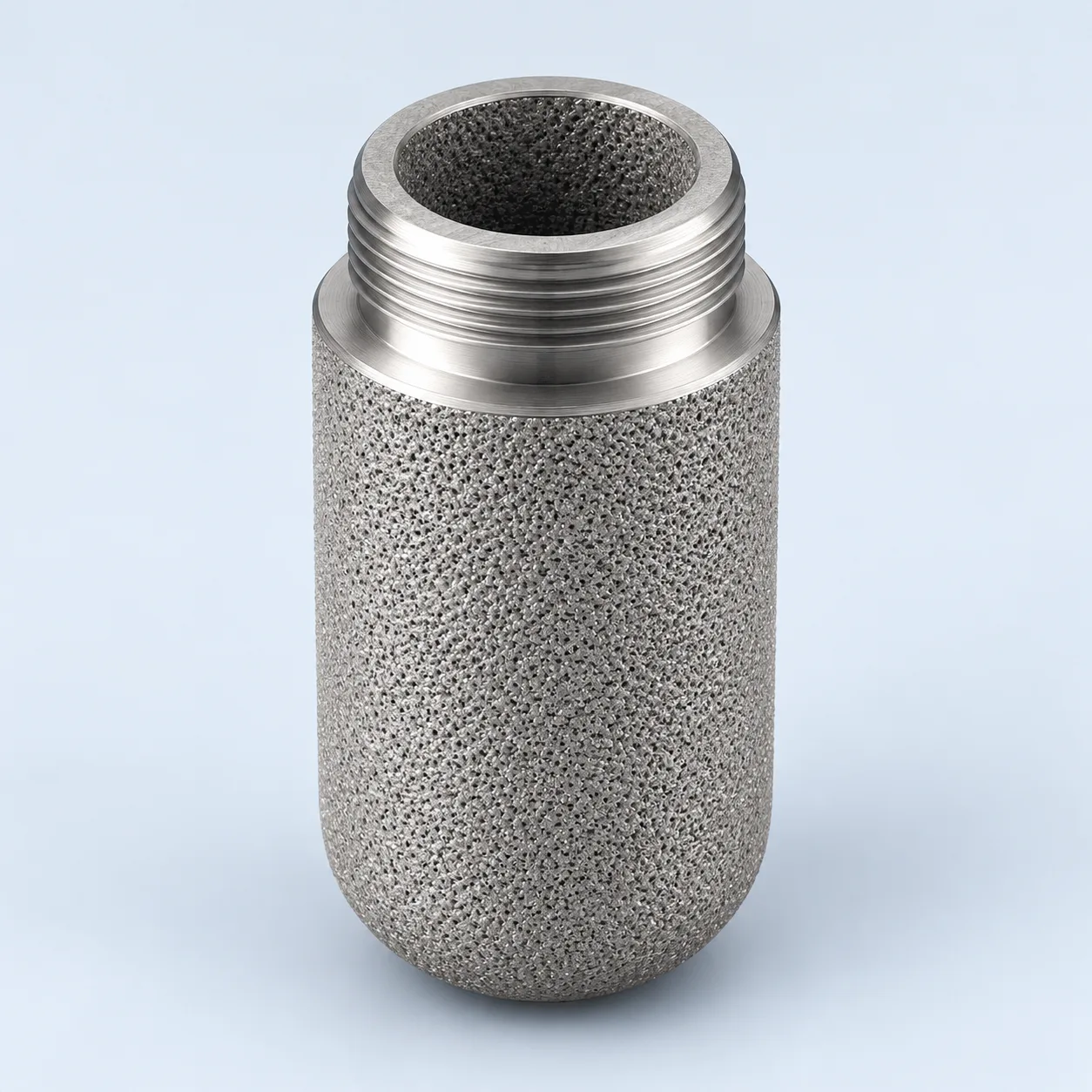
A technical route for instrument and emissions-sampling systems. The complete sampling arrangement and analyzer requirements determine suitability; no accuracy or regulatory-performance claim is made for a generic element.
Porous sampling cup — section

- Filtering wall
The porous cup filters particles from the extracted sample branch. Alloy, retention and interaction with the measured species require confirmation.
- Connection and seal
The cup connection seals the central passage to the sample outlet, preventing unfiltered sample gas from bypassing the wall.
- Clean central passage
Filtered sample gas leaves the bore for the sample line or analyzer. Check analyte recovery and response for the complete sampling train.
- Closed lower end
The illustrated closed end directs sample gas through the wall. Confirm the cup geometry and any approved purge route against the probe or housing drawing.
Heated sample filter — branch installation
A branch draws a gas sample from the process duct to a porous cup in a heated housing. In this selected outside-in layout, solids remain outside the cup and filtered gas leaves its sealed bore for the sample line or analyzer. The heated enclosure is identified without assigning a temperature. Calibration, purge and control provisions follow the actual sampling design. Particle retention does not establish sample representativeness; check analyte recovery and response through the complete train.

- Sample take-off
Only the extracted branch passes through this housing; the drawing does not show filtration of the full duct flow.
- Porous sampling cup
The closed-end cup retains specified particles as sample gas passes from outside to inside.
- Clean-side separation
The cup outlet is sealed through a partition to the sample outlet, preventing an unfiltered bypass.
- Heated enclosure
Heating scope and set points require the sampling-system design. The filter is not a coalescer or an adsorbent.
Probe, heated housing or secondary filter?
A porous metal element may sit at the sampling probe, within a heated filter housing or in a secondary conditioning stage. These locations see different dust concentrations, temperatures and condensate risks. Identify the installation point on the sample diagram and specify which components must remain heated.
In an outside-in design, sample gas crosses the porous wall and the clean stream leaves through the central passage toward the sample line. Solids remain upstream; dissolved or gaseous contaminants are not automatically removed. Flow direction must follow the actual element and housing design. Bypass at an end fitting can undermine the intended protection even when the media itself meets a retention test.
- Locate temperature and differential-pressure monitoring where the system design requires them.
- Distinguish a particulate prefilter from a coalescer or an adsorbent.
- Keep calibration and purge paths visible on the sample diagram.
Specify the sample, not just the micron rating
An element chosen only for fine retention can add avoidable resistance or sample hold-up. Compare the analyzer's required flow and response time with the complete probe, tubing and conditioning train. A component data sheet cannot replace this system check.
On a small screen, scroll the table sideways to see every column.
| Parameter | Unit or definition | Purpose | Input to provide |
|---|---|---|---|
| Particle challenge | µm distribution and mass concentration | Set the protection application | Dust type, loading and downstream tolerance |
| Sample flow | Actual L/min at pressure and °C | Calculate pressure loss and residence effects | Analyzer flow, bypass flow and normal-flow reference |
| Thermal condition | °C and relevant dew points | Avoid unintended condensation | Gas, housing, line and ambient temperatures |
| Gas chemistry | Components, moisture and trace species | Assess corrosion and sample interaction | Analytes, contaminants and wetted-material restrictions |
| Differential pressure | mbar or bar across element | Set maintenance and instrument protection | Clean loss, service threshold and element limit |
| Interface | mm; seal and connection specification | Prevent leaks and bypass | Housing drawing, pressure and leak-test requirement |
Material choice within the sampling train
For an instrument or CEMS sampling element, compare a defined stainless grade with nickel, titanium or a specified nickel alloy only when the sample chemistry justifies it. Review heated surfaces, seals and condensate exposure together. Material availability, particle retention and acceptable sample response must be confirmed for the proposed element and complete sampling train.
Material and surface compatibility
Stainless powder elements are a candidate for compatible gas streams. Corrosive gas or condensate calls for a defined grade and a review of all wetted components, including joints and seals. The availability and behavior of those listed families depend on the actual supplied element.
Porous metal presents internal surface area to the sample. Where an analyte can adsorb, react or be lost in condensate, the complete sample system needs an appropriate recovery or response evaluation. Do not equate a chemically robust alloy with proven analytical neutrality. Heating and cleaning settings must also respect both element and instrument limitations.
- Record the actual alloy and wetted seals.
- Evaluate normal operation and start-up/shutdown condensation.
- Confirm the method for leak checking after service.
Cleaning and inquiry checklist
A purge or reverse-cleaning function must use the conditions approved for the probe and element. After removal, verify fit, cleanliness and the agreed retention or integrity indicator before reuse. Send the sample diagram, gas analysis, dust data, analyzer flow requirement, temperatures and current element drawing. State whether the problem is blockage, corrosion, particle carryover, slow response or unexplained sample loss; those symptoms lead to different investigations.
- Keep maintenance observations with the filter version.
- A catalog micron number is not a CEMS compliance certificate.
Specify the porous cup as part of the heated sample path
Retain the closed-end cup and heated branch shown here. A compact pressed porous component and a long tubular element can have different wall thicknesses, clean volumes and connections even when their labels contain the same micron number. Compare the assembled sample path rather than the label alone.
Particulate protection does not establish unchanged analyte recovery or a flame-arresting function. These are separate requirements with their own verification.
On a small screen, scroll the table sideways to see every column.
| Feature | Selection question | Verification |
|---|---|---|
| Porous wall | Which particles must be held, and at what sample flow? | Efficiency and clean pressure loss under declared test conditions. |
| Cup and fitting | Where are the active wall, dense connection and seal? | Section drawing, leak test and removal access. |
| Heated branch | Could the gas cool below a relevant dew point? | Temperature profile and controlled drainage/maintenance procedure. |
| Measurement response | What dead volume, surface interaction and response time are acceptable? | System-level response and representative-analyte checks. |
- Specify a cleaning method only after checking the cup, joint, seal and sample-service restrictions together.
Specification and acceptance checks
Define protection of the analyzer without assuming that particle retention preserves sample composition. Element-specific flow, retention and differential-pressure values are confirmed for each project; assess the complete heated sampling branch and its leak boundary.
On a small screen, scroll the table sideways to see every column.
| Check | Specify | Acceptance record |
|---|---|---|
| Sample application | Analytes, gas composition and particle challenge | Agreed measurement and material restrictions |
| Thermal boundary | Gas, housing and line temperatures; dew points | Sampling-system temperature schedule |
| Flow and response | Actual L/min, bypass flow and required response | Pressure loss and system response check |
| Sealing | Cup connection, seals and permitted differential pressure | Drawing, leak test and maintenance threshold |
- Retain the closed-end branch-filter arrangement shown here.
- Review unintended condensation and sample interaction separately from dust removal.
Prepare the specification for this application
Use these guides to resolve the next selection questions for this element. Each covers a separate part of the specification.
Product family: Sintered metal powder filter elements
- Gas flow basis for sizing sintered metal gas filters
State sample-flow conditions separately from the main process-gas stream.
- Sintered filter material selection: 316L, titanium and special alloys
Review the porous material and joints against the sample chemistry.
- Sintered metal filter RFQ checklist
Use the inquiry checklist to record the sampling layout and the checks required by the analyzer.