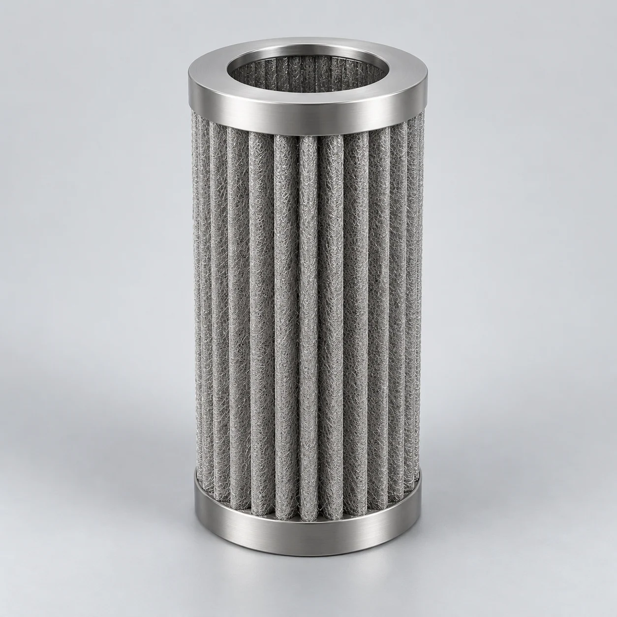
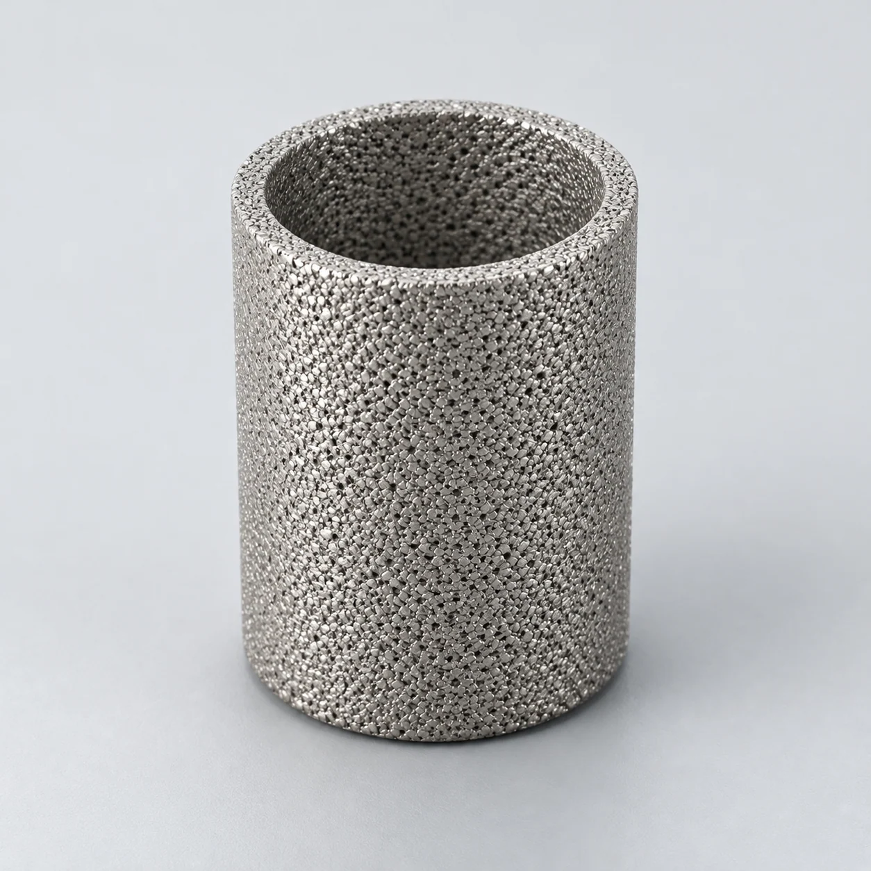
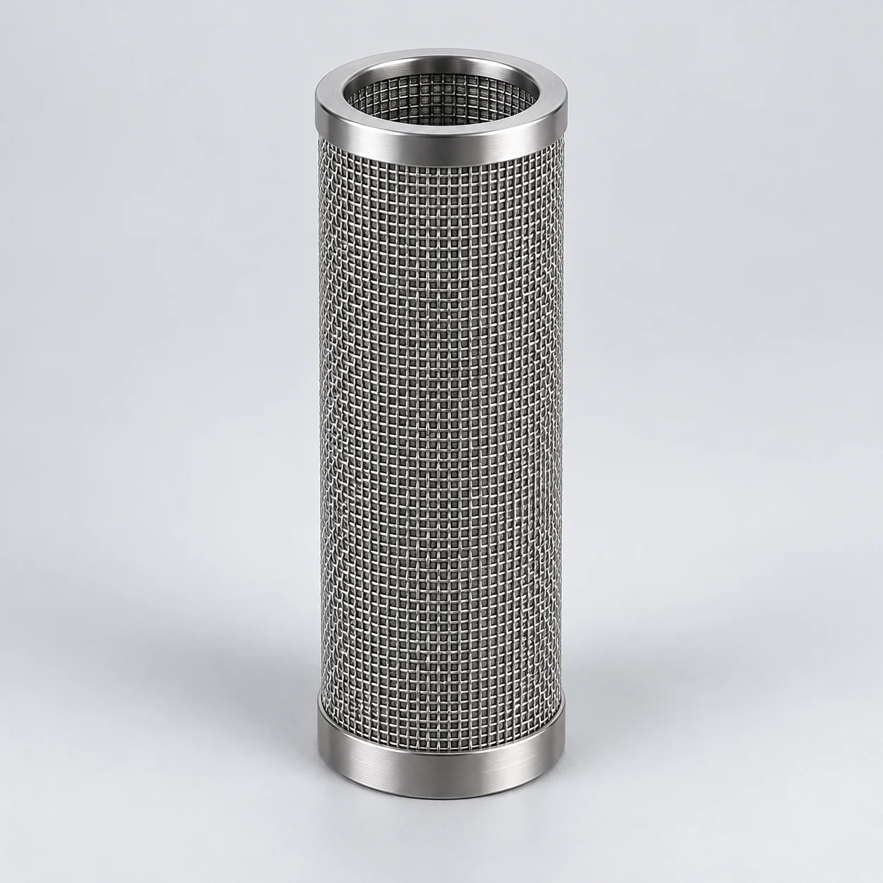
Sintered metal filters for pharmaceutical processes

Start with the equipment function: powder retention, steam-particle control and liquid prefiltration are different selection routes. The detailed element guides below help you move from the equipment application to installation checks and an inquiry. Medical gas components require a separate intended-use review.

Porous sintered metal powder filter element

Find the element guide for your equipment

Choose the closest equipment application, then check the matching element structure and installation. For a different application, use the equipment review below or send the information you have.

Where the element works in the equipment

Follow the equipment position and separation mechanism, then compare the conditions and evidence needed for selection. These are reference applications, not YUNSHENG installation records.

Fluid-bed dryer, granulator or coater: process-powder filter

Element positionIn the process-filter chamber above the product bed, in the gas path leaving the processing vessel; distinct from inlet-air treatment and the distributor plate.

How the element works

Gas passes through the porous filter while entrained powder is retained. In a suitable granulation or drying cycle, sequential reverse cleaning can return captured material to the bed. A coating process may instead require fines to be removed. The equipment's process recipe determines the destination of the collected powder.

Process-filter bank above a fluid bed

Blue arrows show the filtration path shown: process air rises from the bed, crosses the outside of the metal cartridges and leaves through their bores and the clean-gas chamber. Dots mark entrained powder and retained material. Reverse cleaning is not shown. Actual flow direction and mounting follow the equipment drawing.

  1. Process-air inlet

    Air enters below the distributor and moves upward. Inlet-air conditioning and inlet filtration are separate equipment functions.

  2. Product zone

    The air fluidizes the product; entrained powder travels toward the process-filter chamber.

  3. Metal cartridge bank

    The illustrated outside-in arrangement retains powder outside the porous walls; the bores open into the upper clean chamber. Seals must prevent bypass.

  4. Gas outlet

    Gas leaves the clean chamber. The process filter alone does not establish sterile-air quality, containment or a verified emission limit.

Typical operating conditions

  • Batch gas flow and humidity change as wet granules dry; dust loading and stickiness also change.
  • Normal filtration and short reverse-cleaning pulses impose different differential-pressure directions.
  • Product contact, solvent exposure and subsequent washing must be reviewed together.

Selection decisions

Retention and airflow
Define the powder distribution and permitted carryover, then compare candidate mesh or powder constructions using retention and pressure-drop evidence at the required gas conditions.
Cleaning and support
Check the OEM mounting, support, seals and forward/reverse differential-pressure limits. A rigid metal body alone does not establish pulse durability.
Product changeover
Specify residue acceptance and inspection access. If clean-in-place is required, demonstrate cleaning of the actual assembly and recipe rather than assuming it from the material.
Verification and application limits

What to verify

Agree a representative powder trial covering carryover, airflow stability, pressure-drop development and residue removal after cleaning, using the equipment owner's acceptance criteria.

Application limits

This process filter is not automatically an inlet HEPA filter, sterile barrier, gas distributor or verified containment system. Replacement requires the equipment manufacturer's interface review.

Process-steam station: metal-element filter housing

Element positionIn the steam branch serving the specified process equipment or sterilization supply, with upstream condensate separation and drainage appropriate to the installation.

How the element works

Steam crosses a porous metal element to retain defined entrained particles such as rust or valve debris. In the outside-to-inside example illustrated, filtered steam leaves through the element bore; condensate leaves through a separate trapped drain. Typical housings include single- and multiple-element arrangements. Direction, sealing and drainage must follow the selected equipment design.

Multi-element steam-filter housing

Blue arrows show steam entering the dirty side, crossing the metal media from outside to inside and leaving through the clean collection chamber. The dashed lower path is a condensate drain, not a filtered-steam outlet. This original generic layout combines filtration and condensate separation; component interchangeability requires a separate dimensional and functional check.

  1. Steam inlet

    Steam reaches the shell side after the required upstream separation and conditioning; the actual installation defines those stages.

  2. Porous metal elements

    In the illustrated outside-in arrangement, particles are retained at or within the media while steam enters the internal bores.

  3. Filtered-steam outlet

    The element bores communicate with the clean collection chamber. Sealing and steam-quality requirements need their own verification.

  4. Condensate drain

    Collected condensate is routed to a correctly selected trap/drain arrangement. The symbol does not specify trap capacity or a complete steam-station design.

Typical operating conditions

  • Steam demand and condensate formation change during warm-up, intermittent use and shutdown.
  • Steam pressure and condition determine volumetric flow; required mass flow alone does not size the element.
  • Pressure reversals, cleaning exposure and seal ageing require review alongside normal operation.

Selection decisions

Define the steam application
Identify particles and downstream acceptance; distinguish particle control from the steam-quality attributes required by the process.
Size usable area
Assess retention evidence and steam-flow resistance at the stated conditions; verify element count, support and forward/reverse differential-pressure limits.
Review drainage and contact
Check condensate removal, seal interfaces, contact documentation and the equipment owner's release criteria for the complete assembly.
Verification and application limits

What to verify

Agree retention and pressure-drop evidence, installed drainage checks and commissioning observations under representative demand, including warm-up.

Application limits

A particle filter does not create validated clean steam or establish sterility, endotoxin removal or sterilization effectiveness. Those are separate process requirements.

API liquid-transfer or clarification skid: enclosed filter housing

Element positionIn a closed liquid line after a reaction or carbon-treatment stage and before the next specified processing vessel or downstream filtration step.

How the element works

A pressure difference drives liquid through the metal medium while suspended catalyst, activated carbon or other defined particles are retained. The arrangement may collect solids as a cake for discharge or use a polishing application at lower loading. The required filtrate quality and solids-handling sequence determine which arrangement is appropriate.

Typical operating conditions

  • Recipe, solvent composition and temperature affect viscosity, corrosion exposure and available flow.
  • Catalyst or carbon loading can vary through the batch; fine fragments may behave differently from the bulk solids.
  • Cleaning, draining and product-changeover conditions may be more demanding than normal transfer.

Selection decisions

Downstream requirement
Define particulate acceptance and test method before selecting a pore or retention label. Clarification and protection of a later membrane are different objectives.
Media and complete assembly
Compare a proposed metal construction against filtrate quality and permeability. Review alloy, joints, seals, drainability and contact documentation for the complete assembly.
Batch completion
Calculate the pressure-drop budget at the relevant viscosity, then test loading, solids discharge, product hold-up and the proposed cleaning sequence.
Verification and application limits

What to verify

Use representative batch liquid to measure filtrate particles or solids, throughput and pressure drop through a full cycle; agree sampling and post-cleaning release checks.

Application limits

Particle separation does not demonstrate dissolved-metal removal, sterility or API quality compliance. Those endpoints require their own process-specific evidence and validation.

Respiratory or anesthesia equipment: gas-control component development

Element positionWithin an OEM-defined gas-control module, where the device design requires a particle-filtering element, a flow restrictor or separately verified combined functionality.

How the element works

A porous body contains many interconnected flow paths. In a filtration application those paths retain particles according to an agreed challenge test; in a restrictor application their resistance is designed to produce a specified pressure–flow relationship. Shared construction does not make these two performance requirements interchangeable.

Typical operating conditions

  • Gas identity, supply-pressure variation, outlet pressure and temperature influence the pressure–flow relationship.
  • The device may require assessment of short flow transients as well as steady operation.
  • Cleaning, sterilization exposure and direct or indirect patient contact depend on the intended device.

Selection decisions

Define the function
Specify filtration efficiency separately from flow restriction. For a proposed powder component, obtain a measured gas-specific curve rather than substituting a pore-size value.
Control the interfaces
Review the porous-to-solid joint, dimensions, leakage, cleanliness and particle shedding with the device design team. Specify gas reference conditions for every reported flow.
Assign verification
Record intended use, contact nature and duration, abnormal conditions and applicable evidence requirements. The device manufacturer must define the risk assessment and acceptance plan.
Verification and application limits

What to verify

The OEM-led plan should address pressure–flow tolerance, any claimed filtration, leakage, shedding, exposure effects and device-level performance under the defined use conditions.

Application limits

This is engineering reference information. It does not state suitability for patient-contact, life-support, oxygen or sterilizing applications.

Vacuum powder conveyor: receiver filter assembly

Element positionIn the upper filter section of the conveying receiver, between the powder collection volume and the vacuum generator; separate from inlet-air and optional final-stage filters.

How the element works

Suction draws powder and conveying air into the receiver. Product separates into the receiving volume while air crosses the internal filters toward the vacuum outlet. In the arrangement described here, fines collect on the outside of the elements; an inside-out air pulse releases deposits at the end of a conveying cycle. Pleated stainless steel and non-metal constructions require different media and cleaning checks.

Typical operating conditions

  • Fine fraction, moisture and cohesion affect deposits, bridging and the area that remains available.
  • Pipe length, bends and material feed influence conveying demand and available suction.
  • Repeated filling, pulse cleaning and discharge create a cyclic application rather than steady gas flow.

Selection decisions

Balance transfer and retention
Define powder carryover acceptance and conveying rate, then compare the pressure-drop and retention evidence of a qualified metal construction.
Check mounting and cleaning
Confirm filter plate, seals, support and pulse arrangement; assess access, product changeover and residue removal for the installed assembly.
Assess the whole system
Review separate containment, ignition-risk controls and any second-stage filtration with the equipment owner; the internal filter cannot establish these alone.
Verification and application limits

What to verify

Trial representative powder over repeated conveying cycles; record transfer stability, outlet carryover, pressure-drop recovery and post-cleaning residue.

Application limits

A pleated stainless filter is not automatically sintered mesh, a gas distributor, a sterile barrier or a validated containment solution. Specify construction and required evidence before replacement.

A selection sequence for this industry

  1. 1. Define the equipment function

    Identify whether the element retains process powder, clarifies a liquid or performs a medical-device function. Mark the installation point and flow direction on the equipment drawing; keep filtration, gas distribution and flow restriction distinct.

  2. 2. Connect the application to measurable acceptance

    Define the feed, the required downstream condition, available differential pressure and cleaning exposure. Then compare candidate constructions using relevant retention and flow data rather than selecting from a nominal micron rating alone.

  3. 3. Confirm evidence and responsibilities

    Agree trials, contact documentation and post-cleaning checks with the process or device owner. The proposed element needs its own verification and acceptance for the intended installation.

Define the operating envelope

Use actual process conditions, including start-up, shutdown and cleaning. A normal operating point does not describe every load on the element.

Contact and intended use
Process utility, product contact or medical-device fluid path; include contact medium and duration where relevant.
Contamination target
Particles, powder carryover or a flow-control requirement; state the measurement and acceptance method.
Cleaning sequence
Chemicals, concentration, temperature, hold time, rinse and drying steps; include the intended number of cycles.
Documentation
Drawing revision, material identification, cleanliness criteria, traceability and agreed sample inspection.

Define acceptance before selecting a solution

Verify retention and flow separately

Define the particle acceptance target and the required flow-pressure behavior. Passing one does not establish the other.

Assess the finished contact system

For device use, biological evaluation depends on the nature and duration of contact. An alloy name alone does not establish the suitability of a finished component.

Recheck after the agreed cleaning cycle

Compare the sample with its initial condition using the selected hydraulic and integrity checks; add cleanliness criteria relevant to the process.

Prepare the pharmaceutical filtration specification

Use these guides to define acceptance, cleaning and the information to send with your first request.

Questions before selection

Is a metal element automatically a sterilizing-grade filter?

No. Material and nominal pore descriptions do not establish sterile filtration. A sterile-process claim requires a defined application and the relevant performance validation.

Can a process filter be used directly in a medical device?

The component role, contact pathway and finished-device verification must be assessed separately. A process-filtration specification is not a medical-device qualification.

What should be included with an initial inquiry?

A process sketch, fluid and particle description, operating cycle, connection drawing and intended verification requirements provide a useful starting package.

Discuss the element in its pharmaceutical process

Send the equipment function and the requirement you need to meet. A drawing, cleaning procedure or existing element description can help; unknown values can remain open.

Inquiry contextSintered metal filters for pharmaceutical processes

Useful if available — optional for your first inquiry:

  • Equipment type and whether the element retains powder, filters steam, clarifies liquid or serves another function.
  • Process fluid or powder, operating conditions and product-contact requirements already defined by your team.
  • Available drawing or existing-element details, with the required cleaning or sterilization exposure identified separately.
Request a quote

Use the full inquiry form to attach a drawing or file. The short form alongside accepts your message.

Regarding: Sintered metal filters for pharmaceutical processes

Send a message

* Required. For drawings and operating conditions, use the full inquiry form. Open technical inquiry

Continue in this tab. Your entered contact details and message are transferred once; consent must be given again.

Name & company · optional
Privacy information — read here

Your contact details and requirements are used to respond to your inquiry.

Opening privacy information keeps this form in its original tab. Files must be selected again after a reload.

Privacy information