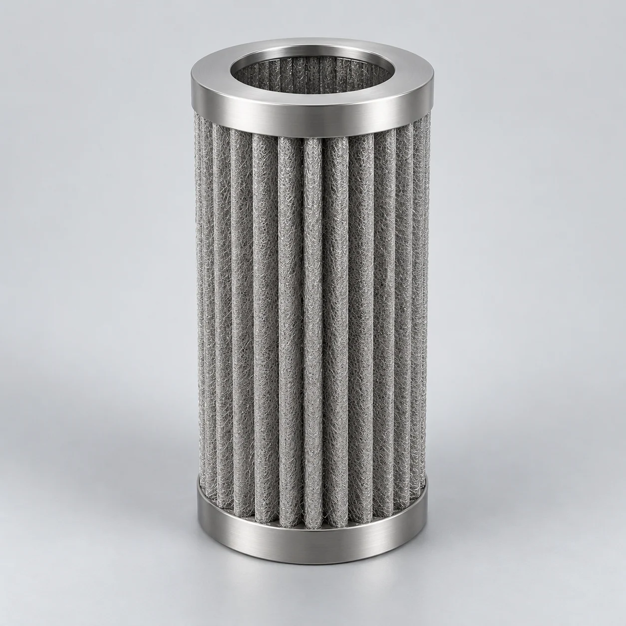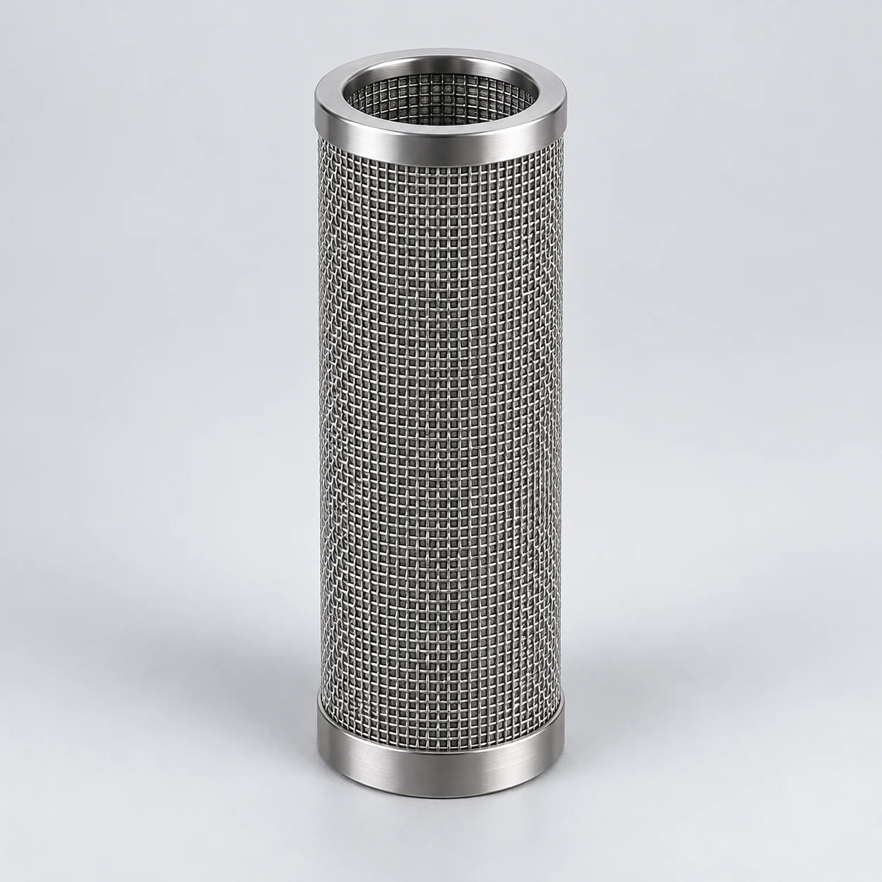
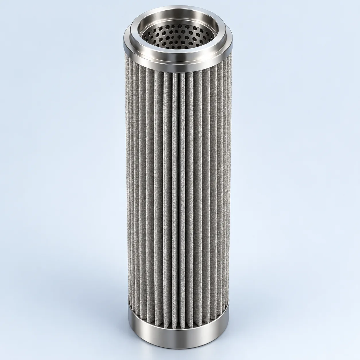
Define the polymer and heated-housing arrangement first. Confirm temperature, forward/reverse differential-pressure limits, retention, effective area and cleaning acceptance for the proposed element.
Pleated metal-fiber candle — medium and support

Pleated metal-fiber candle — medium and support. Numbered connections, filtering medium, clean passage and closure are identified.
- End connection
The connection and seating must match the melt housing.
- Pleated melt-filter medium
The folded metal-fiber medium is shown with support; usable flow area and pleat geometry require the controlled drawing.
- Filtered-melt passage
The internal support carries the medium while filtered polymer melt enters the bore and flows toward the clean collector.
- End closure
The joint closes the unfiltered bypass route at the end.
Heated polymer-melt candle housing
One selected equipment arrangement is shown to explain position and flow. Verify actual flow, connections, seals and operating sequence against the equipment drawing.

- Heated housing boundary
The housing heat system and thermal profile require equipment-level review.
- Pleated fiber candles
Melt flows through the pleated medium and support into the clean passage.
- Filtered-melt outlet
The clean collector leads toward downstream spinning or extrusion equipment.
- Candle lower closure
End closures and seating must prevent a bypass around the filtering medium.
Product images
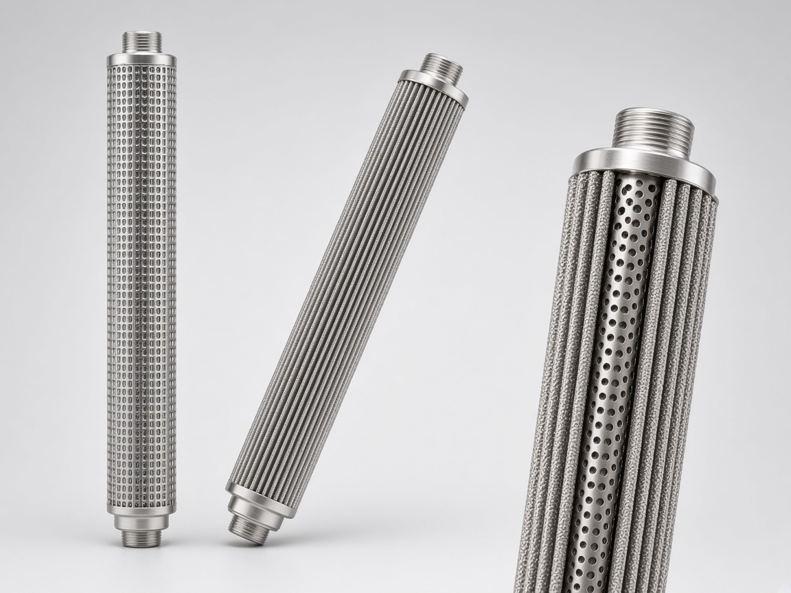
Where the candle works
Multiple filter candles may connect to a tube sheet or filtrate manifold inside a heated pressure housing. Their role is to intercept specified contamination before downstream spinning or extrusion equipment. Verify whether the proposed housing uses candles, disc stacks or another format before preparing a replacement drawing.
Pleated metal-fiber media combine a three-dimensional pore network with a larger surface area within the cartridge envelope. They are candidates for viscous polymer streams and gel or particle removal. Compare pressure loss, usable area, support and cleaning performance rather than assuming that similarly sized melt cartridges are interchangeable.
Distinguish gels from hard particles
A bonded fiber network provides depth-loading paths; pleats add geometric area within a limited envelope. The useful area also depends on pleat spacing, supports, welds and how the melt reaches the medium. Hard particles, deformable gels and degraded polymer may behave differently under shear and pressure.
A finer label can increase resistance without solving a gel problem. Specify the downstream defect to prevent and assess representative melt or contamination evidence. Flow distribution and stagnant pockets matter because a replacement that creates residence-time problems can generate new degradation deposits.
A melt-filter technical schedule
On a small screen, scroll the table sideways to see every column.
| Parameter | Unit or evidence | What to compare |
|---|---|---|
| Throughput and melt state | kg/h; temperature; viscosity data | State polymer grade, normal range and startup conditions. |
| Contamination objective | Gel/particle description; test result | Separate hard-particle retention from deformable-gel control. |
| Filtration grade | µm with declared test basis | Compare removal evidence, not nominal numbers in isolation. |
| Usable area | m² and calculation boundary | Exclude covered supports, weld margins and inaccessible pleat zones where applicable. |
| Pressure loading | bar; temperature-specific limits | Separate clean loss, terminal forward ΔP and reverse cleaning loads. |
| Installation and heat exposure | Drawing in mm; thermal profile | Match manifold seating, candle spacing, expansion allowance and heated envelope. |
| Cleaning recovery | Method; residual contamination; flow test | Agree polymer removal, damage inspection and reacceptance. |
Match alloy to the polymer and cleaning route
Evaluate 316L only against the actual melt additives, degradation products and regeneration chemicals. Special nickel-based grades can be considered when a defined corrosion or thermal mechanism excludes stainless steel, but fiber availability, weldability and support compatibility must be established for the proposed construction.
Do not adopt a generic high-temperature alloy limit as a melt-filter operating limit. The complete assembly, mechanical loading and exposure time control the decision.
Request a comparable trial and controlled cleaning route
Ask for the element drawing, fiber construction description, material traceability, clean-flow data with fluid conditions, retention basis and forward-load verification. Where service history is unavailable, define a trial measuring pressure rise, defect rate and throughput against the same feed conditions.
Cleaning must remove deposits without opening the structure, cracking welds or distorting pleats. Record the approved sequence and inspection criteria; compare post-cleaning flow and integrity with the original baseline. Burning, chemical dissolution and ultrasonic methods are not interchangeable default instructions.
- Send the original candle connection and housing arrangement.
- Identify the dominant defect and how it is measured.
- Provide the existing cleaning recipe and observed failure mode.
Confirm candle-bank and disc-stack interfaces before replacement
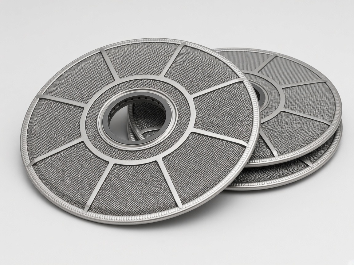
A vertical candle bank and an annular disc stack solve the installation problem differently. A candle review covers the manifold connection, inner and outer supports, filtering layer and locating end closure. A disc-stack review covers the center-post interface, disc support, stack height and clamping arrangement. A shared metal-fiber medium does not make these formats interchangeable.
Some spinning-line applications involve a solvent-containing precursor solution rather than a polymer melt. Identify the actual polymer, solvent if present, concentration and operating state before using a melt-filter specification. Define hard contaminants and deformable gels separately; the selected medium and cleaning procedure need to match the real fluid.
- Mark normal flow, clean-side outlet and the seating details on the equipment drawing; do not infer flow direction from the element format or a catalog image.
- For a jacketed disc housing, identify the process cavity and heating circuit separately. Confirm the heat-transfer medium and its conditions without treating jacket pressure as element differential pressure.
- Agree removal clearance, lifting support and the approved clamping procedure. A hydraulic assembly-tool gauge is not a process-pressure or filtration-resistance measurement.
- After the agreed cleaning and drying sequence, inspect supports, joints and sealing faces, then repeat the specified integrity and clean-flow checks before reinstalling the element.
Specification and acceptance checks
Approve the complete heated candle assembly, including its manifold connection and usable pleated area. A clean-air media result is not a melt-throughput rating; compare proposals using the same polymer, temperature and contamination target.
On a small screen, scroll the table sideways to see every column.
| Check | Specify | Acceptance record |
|---|---|---|
| Melt application | kg/h, polymer grade and temperature profile | Shared feed and viscosity basis |
| Geometry | Connection, heated length, pleat support and spacing | Controlled candle/manifold drawing |
| Loading | Clean loss and terminal differential pressure at temperature | Element and joint load evidence |
| Reacceptance | Approved deposit-removal sequence | Post-cleaning flow, weld and pleat inspection |
- Separate hard-particle removal from the agreed gel-defect objective.
- Do not compare permeability values without their test pressure, area and medium.
Typical specifications
On a small screen, scroll the table sideways to see every column.
| Component / parameter | Typical execution |
|---|---|
| Media | Pleated fibre felt, multilayer mesh or sintered powder |
| Construction | Connector, inner perforated core, media, outer guard cage, locating end cap |
| Rating, µm | 3–100 (βx ≥ 75) |
| Material | 316L; 310S on request |
| Operating temperature | up to 300 °C |
| Allowable forward ΔP | up to 10 MPa (reference; confirmed per design and housing) |
| Dimensions / connection | to housing drawing (thread, flange or plug-in) |
| Cleaning | Thermal/solvent cleaning, then bubble-point check |
Reference values only; final specifications are confirmed for each custom order.
Prepare the specification for this application
Use these guides to resolve the next selection questions for this element. Each covers a separate part of the specification.
Product family: Sintered metal fiber filter elements
- Sintered mesh vs sintered powder vs metal fiber felt: how to compare
Distinguish a fiber pleat pack from a woven-mesh alternative before comparing elements.
- Sintered metal filter pressure drop and flow area
Compare effective area and melt resistance at the actual viscosity and temperature.
- How to clean sintered metal filters safely
Review polymer removal against the pleats, support core and end connections.