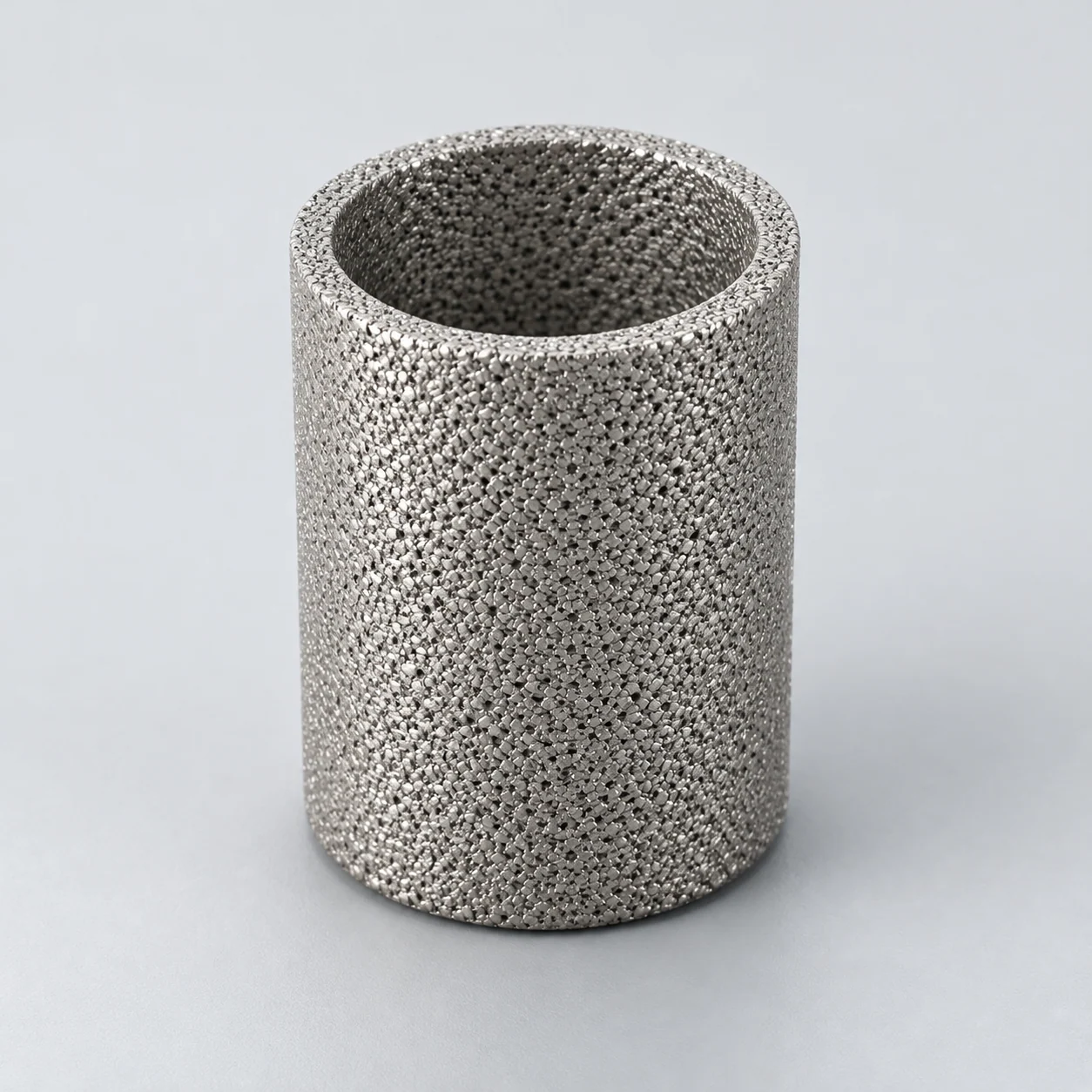
Sintered metal filters for chemical and petrochemical processes

Identify the separation step before comparing media: catalyst recovery, polymer-melt filtration and pressure-leaf clarification use different assemblies and operating cycles. Use the linked element guides for the selected configuration, then compare the wider equipment applications and preparation checks on this page.

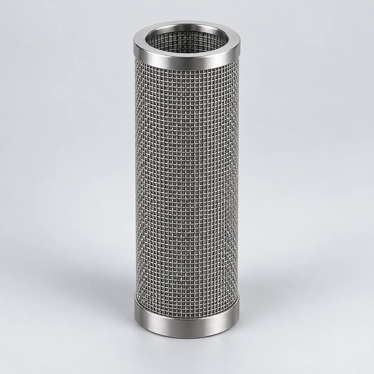
Cylindrical sintered wire mesh filter element

Choose the chemical-process element route

Start with the equipment and the stream you need to separate. The detailed guides cover one configuration per route, rather than treating all chemical filtration as interchangeable.

Where the element works in the equipment

Follow the equipment position and separation mechanism, then compare the conditions and evidence needed for selection. These are reference applications, not YUNSHENG installation records.

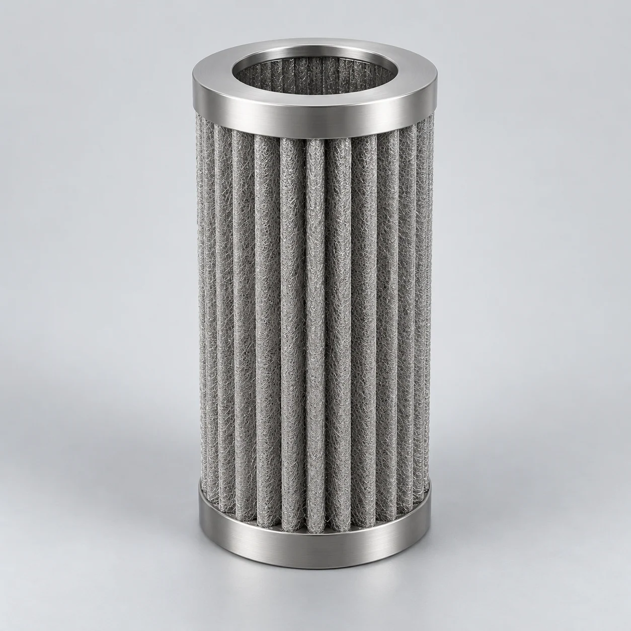
Extrusion or fiber-spinning line: polymer-melt candle filter

Element positionIn a heated melt-filter housing before a specified downstream operation such as an extrusion die or spinning assembly; the exact order of pump, filter and other components is equipment-specific.

How the element works

The melt passes through supported metal media while contaminants are retained. Mesh provides a surface-screening route for defined hard particles; fiber media provide a depth-capture route that must be evaluated for the actual contamination. Candle geometry increases installed area, but flow distribution and support determine how much of that area is useful.

Heated polymer-melt candle housing

Blue arrows illustrate an outside-in candle arrangement: melt enters the surrounding chamber, crosses the supported metal media and travels along the inner passages to the outlet. Dots on the dirty side indicate contamination. The outer border represents a heating jacket, not a second product-flow channel. The flow direction shown must be checked against the housing drawing.

  1. Melt inlet

    The polymer stream enters the chamber around the candles. Pump position and thermal conditioning belong to the process design.

  2. Supported metal candle bank

    Particles meet the porous media before the melt reaches the inner passages. The diagram does not equate surface mesh and depth-type fiber media.

  3. Clean collection and outlet

    Inner passages open into a separate collection chamber. Connections, seals and support prevent a route around the media.

  4. Heating jacket

    A conceptual thermal-control envelope surrounds the housing. Heating-medium piping and temperature-control design are omitted.

Typical operating conditions

  • Polymer grade, temperature and shear-dependent viscosity influence resistance and processing behavior.
  • Hard particles, degraded polymer and deformable contamination may require different evaluation methods.
  • Heat-up, shutdown and cleaning impose thermal and mechanical conditions beyond steady production.

Selection decisions

Relate retention to quality
Define the defects to control and how they will be measured in melt or finished product. Do not infer gel removal from a family name or pore measurement.
Review hydraulics and geometry
Assess throughput, viscosity, usable media area, pleat spacing and support against clean and terminal differential pressure, including the permitted flow direction.
Plan thermal exposure
Review temperature uniformity, residence-time concerns, seals and the proposed cleaning procedure with the equipment owner; verify element condition before reuse.
Verification and application limits

What to verify

Evaluate the proposed construction under representative melt conditions; track product defects, pressure-drop development and post-cleaning integrity using agreed acceptance criteria.

Application limits

Gel-removal efficiency, pressure tolerance and service life depend on the media grade, support and actual process, and require configuration-specific verification.

Pressure-leaf vessel: multi-leaf solid–liquid separation

Element positionMultiple double-sided leaves are mounted inside a closed pressure vessel and connected to a filtrate manifold, with a separate route for cake discharge.

How the element works

Feed surrounds the leaves. Liquid passes through the filtering surface and deposited cake into each leaf's internal drainage channels, then exits through the clean manifold. A selected precoat or cloth may provide the controlling retention layer, while metal mesh provides support and drainage. Cake is removed in a separate wet-discharge or dry-discharge sequence suited to the material.

Pressure-leaf bank with internal filtrate drainage

Blue arrows show feed surrounding the leaves, liquid crossing both faces and filtrate draining internally to a common manifold. The right-hand inset enlarges one leaf section: dots represent cake/precoat outside the metal support. Bottom discharge is closed during the filtration phase shown; cake discharge occurs in a separate cycle.

  1. Suspension inlet

    Feed fills the vessel around the leaf bank. The housing must distribute the suspension without relying on an unverified element count.

  2. Double-sided leaves

    Each leaf combines outer filtering/support faces and inner drainage. Expanded view shows the two sides; the metal construction is not automatically sintered mesh.

  3. Filtrate manifold

    Internal drainage from the leaves joins the clean collection route and outlet.

  4. Cake or precoat barrier

    In a precoat process the deposited layer provides the separation barrier and the metal leaf supports it. A screen opening alone does not define the process retention.

  5. Separate cake-discharge route

    The bottom closure is shown shut during filtration. Cake removal follows the equipment-specific isolation, draining and discharge sequence.

Typical operating conditions

  • Suspended-solids concentration, fine fraction and cake compressibility affect resistance and cycle capacity.
  • Viscosity, temperature and mixture chemistry affect filtration and material compatibility.
  • Cake growth reduces available space between leaves; draining, washing and discharge alter the operating conditions.

Selection decisions

Identify each layer's function
Specify the retaining screen, support and drainage separately; identify any cloth or precoat and whether filter aid is acceptable in the recovered solids.
Review usable area and cake space
Check leaf spacing, manifold sealing, area, pressure drop and batch completion together instead of selecting by mesh opening alone.
Plan solids discharge
Match cake release and washing to the feed; confirm frame condition, joints, seals and the actual assembly drawing.
Verification and application limits

What to verify

Use representative slurry to assess filtrate clarity, cycle throughput, cake release and leaf integrity, including the proposed precoat and cleaning sequence.

Application limits

Woven wire leaves are not automatically sintered-mesh elements. Precoat performance cannot be assigned to the bare metal support, and a generic cartridge is not a leaf replacement.

Stirred-tank reactor: external catalyst-recovery loop

Element positionIn a pumped slurry recirculation loop connected to a continuous stirred-tank reactor, with a separate filtrate outlet and a route for returning or discharging concentrated catalyst.

How the element works

Liquid crosses the porous wall while catalyst remains in the circulating slurry. Crossflow and, where designed, reverse pulses can manage deposited cake. The loop can maintain catalyst within a closed process while withdrawing clarified product, but recirculation, backpulse and solids handling must be designed as one system.

Typical operating conditions

  • Catalyst loading and particle distribution change with feed, attrition and catalyst condition.
  • Reaction temperature, liquid viscosity and gas evolution affect filtration and loop operation.
  • Start-up, stopping and cleaning can produce conditions different from steady filtration.

Selection decisions

Retention target
Define catalyst carryover and the required analytical method, including the fine fraction. Evaluate a powder medium with representative slurry rather than matching a micron rating.
Hydraulics and cake
Review transmembrane differential pressure, crossflow, recirculation application and permitted reverse pressure together. More recirculation is not automatically better if it damages the catalyst.
Recovery sequence
Specify catalyst return or discharge, solvent inventory and cleaning compatibility. Confirm the housing, valves and controls support the intended closed operating sequence.
Verification and application limits

What to verify

Progress from a representative-feed feasibility trial to a suitable pilot. Measure filtrate solids, flux, cake release and catalyst condition over the proposed operating cycle.

Application limits

Recovery percentage, cycle length and catalyst activity are evaluated for the actual process. The filter wall alone cannot guarantee continuous reactor operation or safe solids handling.

Solvent or intermediate transfer line: cartridge filter housing

Element positionIn a transfer line between process vessels, after a source of suspended contamination and before the receiving operation whose cleanliness requirement drives the specification.

How the element works

Pressure-driven liquid filtration retains defined suspended particles in or on the metal medium. A mesh structure may be evaluated for surface screening; a porous powder or fiber structure may be compared when its retention and loading behavior fit the task. The medium does not remove dissolved impurities merely because it filters particles.

Typical operating conditions

  • Composition, concentration, trace contaminants and temperature can vary between recipes or campaigns.
  • Viscosity and instantaneous transfer flow determine the hydraulic demand more directly than annual production volume.
  • Flushes, cleaning chemicals, shutdown exposure and liquid hold-up influence material and assembly selection.

Selection decisions

Define the contamination
Identify particles, their source and the downstream acceptance criterion. Separate a low-loading polishing application from a solids-recovery application requiring planned cake discharge.
Check compatibility
Review the full mixture at operating and cleaning conditions, including porous alloy, welds and seals. A statement such as 'solvent service' is not sufficient.
Fit the operating cycle
Compare measured retention, usable area, clean and terminal pressure drop, connection geometry and service access. Include the effect of contamination loading on completion of the transfer.
Verification and application limits

What to verify

Confirm compatibility evidence and perform a representative-liquid trial where needed; record filtrate quality, pressure-drop progression, throughput and acceptance after the proposed cleaning procedure.

Application limits

No universal chemical compatibility, filtration life or reuse interval is implied. Element selection does not establish the pressure rating or chemical suitability of the complete housing.

Polymer extrusion line: rotary melt screen changer

Element positionAcross the heated melt channel inside the screen changer; supported screen packs occupy cavities in a rotary disc between the inlet and outlet blocks.

How the element works

Melt passes through the active screen packs while defined contaminants remain on the upstream side. Disc movement presents other screen areas to the melt channel. In a documented backflushing design, a measured portion of filtered melt passes backwards through a limited dirty-screen segment to a separate waste outlet. Screen indexing, filtration and cleaning are distinct parts of the equipment's controlled sequence.

Typical operating conditions

  • Recycled-feed contamination and polymer grade vary, changing loading and the cleaning demand.
  • Melt temperature, rheology and throughput affect resistance; residence time matters for sensitive polymers.
  • Normal melt flow and reverse cleaning impose different loads on the screen and its support.

Selection decisions

Define the screen pack
Confirm weave, layer order, retaining surface, breaker plate and fit to the cavity. Woven screen packs are not automatically sintered or equivalent to cartridge media.
Relate removal to product quality
Agree hard-particle and deformable-contaminant acceptance separately; a nominal opening alone cannot predict melt-gel removal.
Review the full cycle
Assess active area, melt pressure, thermal exposure, backflush compatibility and waste discharge with the OEM's operating sequence.
Verification and application limits

What to verify

Run representative polymer and contamination through a suitable trial; record product defects, differential-pressure trend, screen condition and material lost during cleaning.

Application limits

Pressure stability, screen life and gel-removal efficiency require equipment-specific qualification of the proposed replacement packs.

A selection sequence for this industry

  1. 1. Define both output streams

    Decide whether success means cleaner liquid, recovered catalyst or controlled melt defects. Record the contaminant and acceptance method; a particle filter cannot be selected to remove an unspecified dissolved impurity.

  2. 2. Match the separation cycle to the equipment

    Choose the proposed filtration arrangement before sizing the element: recirculating recovery, batch transfer and melt filtration have different loading and discharge needs. Review chemistry, viscosity, flow, usable area and differential pressure together.

  3. 3. Validate with the relevant feed

    Use equipment examples to identify candidate constructions, then agree the evidence and representative tests for the actual mixture or melt. Agree filtrate or product quality, cycle completion, solids handling and cleaning acceptance before final selection.

Define the operating envelope

Use actual process conditions, including start-up, shutdown and cleaning. A normal operating point does not describe every load on the element.

Chemistry
Main compounds, concentrations, impurities, phase and the complete cleaning chemistry.
Solids behavior
Size distribution, concentration, shape, abrasiveness, compressibility and any sticky constituents.
Hydraulic cycle
Normal and peak flow, viscosity, temperature variation, clean allowance and terminal differential pressure.
Solids route
Filtration direction, cake capacity, discharge or backwash sequence and permitted product loss.

Define acceptance before selecting a solution

Review actual exposure

Corrosion-table results do not fully represent an impure process stream. Include contaminants and cleaning exposure when selecting materials.

Test a representative feed

Agree which feed conditions the sample represents and how to measure filtrate quality, pressure rise and solids release. Record changes during the run.

Evaluate repeated cycles

A promising first filtration run does not establish reusable performance. Include the proposed cleaning and a repeat run in the acceptance plan.

Resolve the chemical-process selection questions

Compare the media structure first, then define the hydraulic and material evidence needed for the proposed assembly.

Questions before selection

Does a finer medium always improve a process?

A finer retention target may be useful, but the process also needs acceptable pressure loss, cycle duration and recovery. Set the downstream quality requirement first.

Can an alloy be chosen from the chemical name alone?

Provide concentration, temperature, impurities and cleaning exposure as well. A compatibility judgement for a pure laboratory solution may not represent the operating stream.

When is a sample trial especially useful?

When solids are compressible, sticky or valuable, or when the feed changes significantly. A trial should answer a defined selection question rather than only demonstrate clear-looking filtrate.

Bring the process and element requirements together

Tell us the equipment, the material you want to retain or pass, and the process cycle. Include available documents rather than assigning unconfirmed values.

Inquiry contextSintered metal filters for chemical and petrochemical processes

Useful if available — optional for your first inquiry:

  • Equipment and separation objective: catalyst recovery, polymer melt, pressure-leaf filtration or another chemical application.
  • Stream composition, solids or contaminant description, temperature and viscosity if known.
  • Available flow and differential-pressure requirements, drawing, solids-discharge method and planned cleaning exposure.
Request a quote

Use the full inquiry form to attach a drawing or file. The short form alongside accepts your message.

Regarding: Sintered metal filters for chemical and petrochemical processes

Send a message

* Required. For drawings and operating conditions, use the full inquiry form. Open technical inquiry

Continue in this tab. Your entered contact details and message are transferred once; consent must be given again.

Name & company · optional
Privacy information — read here

Your contact details and requirements are used to respond to your inquiry.

Opening privacy information keeps this form in its original tab. Files must be selected again after a reload.

Privacy information