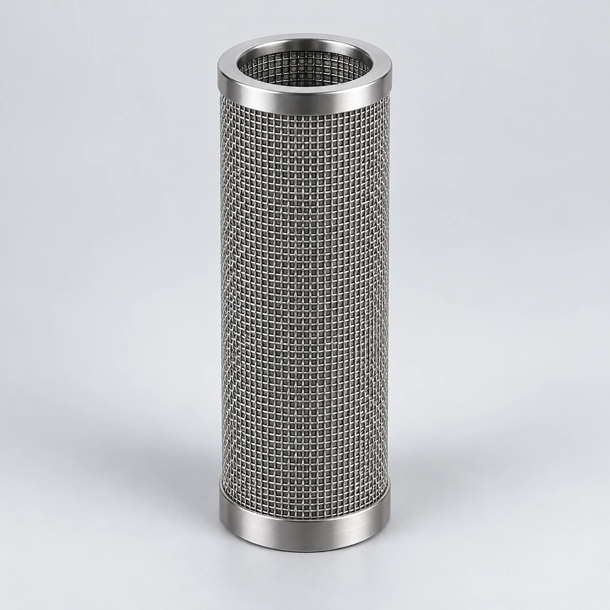
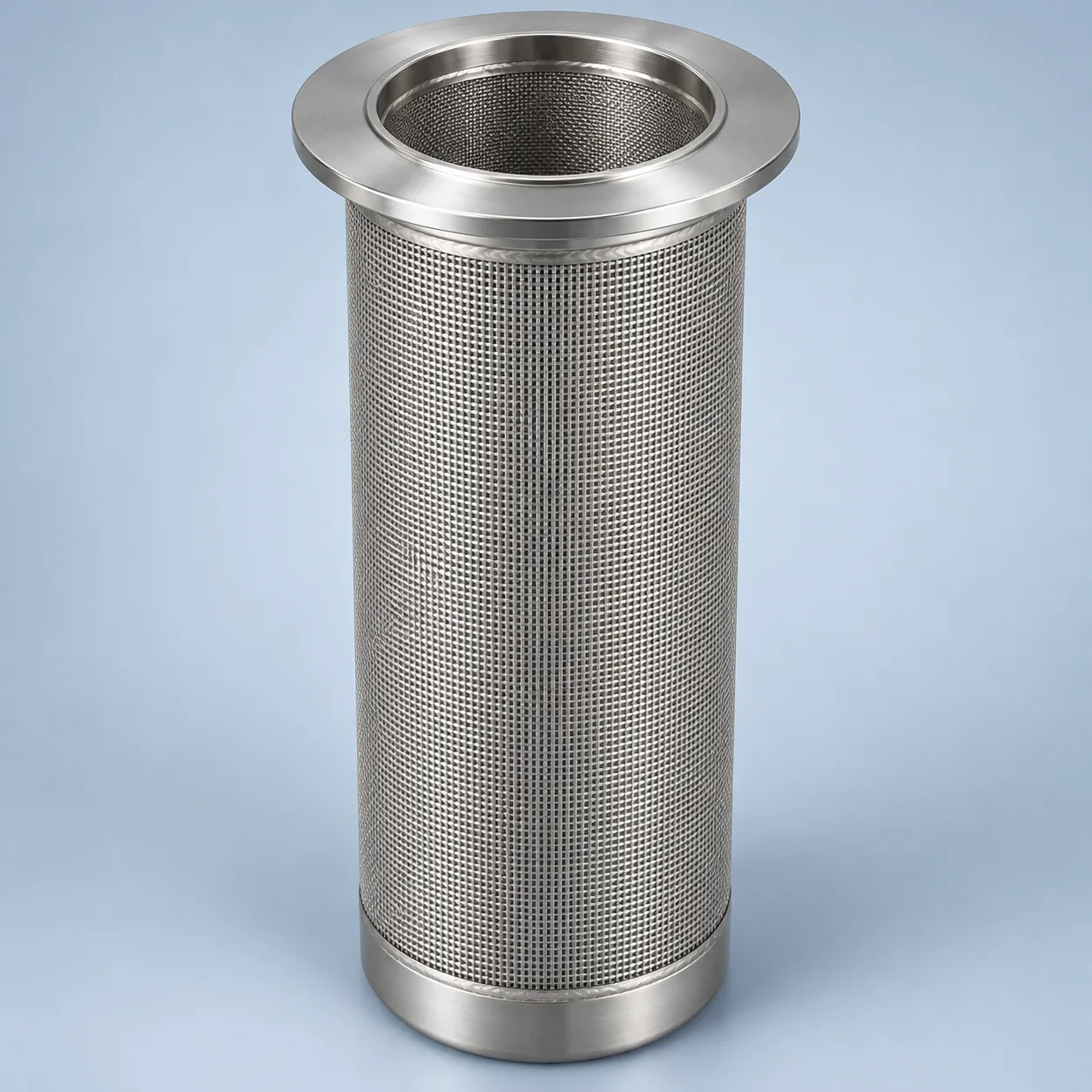
Application engineering guidance. A proposed metal-mesh assembly requires an approved equipment drawing and configuration-specific evidence; no filtration grade, pharmaceutical qualification or replacement compatibility is confirmed here.
Fluid-bed cartridge — mesh wall and bore

- Clean-side mounting connection
The upper connection opens into the clean-gas plenum and seals against the product zone.
- Supported mesh wall
The enlarged section separates the filter layer from its supporting layers.
- Clean process-gas passage
Gas passes through the outside-in mesh wall into the bore, then leaves toward the clean-gas plenum.
- End closure
The closure prevents unfiltered bypass through the lower end.
Fluid-bed product-retention arrangement
The arrows show normal filtration. Reverse-pulse gas flows in the opposite direction during a separate controlled cleaning cycle and is not shown here. One selected equipment arrangement is shown to explain position and flow. Verify actual flow, connections, seals and operating sequence against the equipment drawing.

- Mounting plate and seals
The cartridge connection separates the product zone from the clean plenum.
- Metal product-retention cartridges
The selected outside-in layout retains entrained powder on the outer surface.
- Fluidized product zone
Gas rises from the bed; product-retention filtration is above this zone.
- Clean-gas plenum and exhaust
Gas leaves through the cartridge bores into the separate clean chamber.
Product images
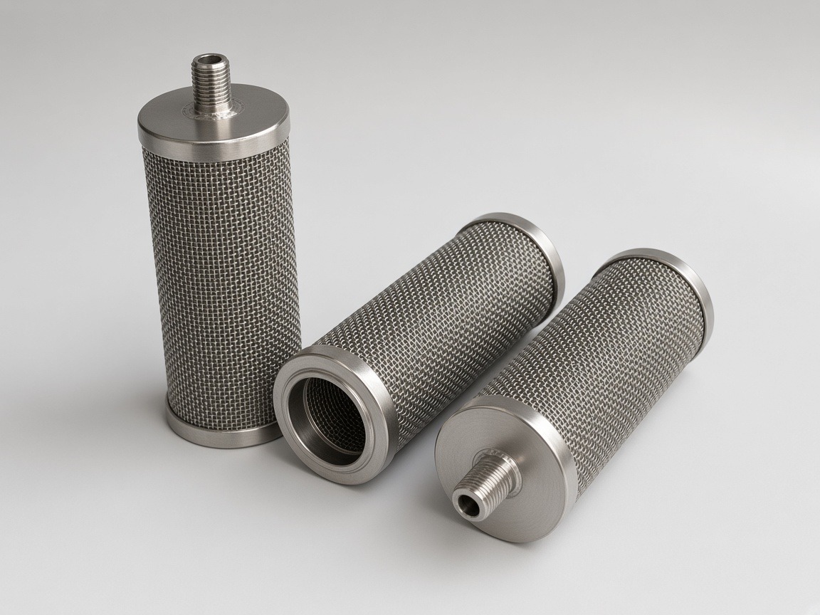
Installation above the product zone
The process filter sits between the fluidized product zone and the exhaust plenum. It limits powder carryover while allowing process gas to leave. In a cartridge arrangement, retained particles can return to the bed during a controlled cleaning cycle. The exhaust path, cartridge mounting and cleaning sequence must match the equipment design.
For a cartridge arrangement, review the mounting plate, clean-side plenum, end seals and retention hardware as one assembly. Do not confuse this filter with the inlet-air final filter, the distributor plate below the bed or a separate exhaust containment stage.
Retention and pulse recovery form one application
In an outside-to-inside arrangement, dusty gas reaches the outer filtering surface and cleaned gas leaves through the bore. Confirm this direction on the actual equipment drawing. Deposited powder increases resistance; a controlled reverse pulse can release it. Mesh opening, cake formation, pulse distribution and seals all affect the result.
Evaluate fines returning to the batch separately from dust escaping downstream. A lower-pressure-drop element is not acceptable if product loss, cross-contamination or cleaning residues exceed the agreed limits.
Operating conditions and technical data to specify
On a small screen, scroll the table sideways to see every column.
| Parameter | Unit or evidence | What must be agreed |
|---|---|---|
| Process gas flow | Actual m³/h; temperature; pressure | Normal and peak gas volume at the filter, not an unexplained standard-volume figure. |
| Powder retention | Particle distribution; mass loss; efficiency | Define the fines challenge and allowable carryover; a µm label alone is insufficient. |
| Operating resistance | Pa or mbar | Clean, loaded and terminal differential pressures at the stated gas flow. |
| Pulse-cleaning conditions | Pressure; duration; sequence | Element reverse-load limit and pulse delivery at each position. |
| Mounting and sealing | Controlled drawing, mm | Plate opening, seating, gasket compression and removal clearance. |
| Cleaning acceptance | Residue limits; inspection method | Wash exposure, drainage, drying and cross-contamination criteria. |
Alloy selection includes washing and drying
Review the mesh, support, welds and end fittings together. A 316L proposal needs a compatibility assessment for both formulation residues and cleaning chemicals. If chloride-bearing or unusually aggressive washing is involved, evaluate a specifically identified higher-alloy alternative such as 904L or a nickel-chromium-molybdenum grade; a premium alloy name does not prove suitability.
The assembly also needs an equipment-level review of grounding, combustible powder and solvent conditions. Metal construction alone does not establish explosion protection.
Agree a measurable replacement trial
Request the current drawing revision, material traceability, weld and leak checks, retention test basis and forward/reverse-load evidence. Establish a clean airflow baseline before the trial, then compare resistance, carryover and cleanliness after the agreed wash sequence. WIP or CIP suitability must be demonstrated for the installed arrangement.
- Send the original element dimensions and photographs with sensitive project details removed.
- Record powder characteristics, gas conditions, pulse settings and cleaning recipe as separate inputs.
- Define trial acceptance and inspection responsibility before ordering a replacement batch.
Specification and acceptance checks
Approve the mounting and cleaning conditions together. A replacement must preserve the tube-sheet seal and removal access while meeting the agreed powder-containment target after the intended wash and pulse sequence.
On a small screen, scroll the table sideways to see every column.
| Check | Specify | Acceptance record |
|---|---|---|
| Mounting | Seat, gasket compression and clearance; mm | Controlled element and tube-sheet drawings |
| Gas application | Actual flow, temperature and clean/loaded resistance | Airflow baseline with test conditions |
| Powder containment | Fines challenge and downstream carryover limit | Representative-powder trial |
| Cleaning cycle | Wash recipe, pulse sequence and drying | Post-cycle inspection and residue result |
- Check reverse-pulse loading separately from vessel operating pressure.
- Release the replacement only against the agreed drawing revision and trial criteria.
Typical specifications
Retention elements and fluidizing plates perform different functions. Read the two reference forms separately and identify the function required by the equipment drawing.
On a small screen, scroll the table sideways to see every column.
| Form (model) | Typical dimensions | Rating, µm | Media temperature range | Notes |
|---|---|---|---|---|
| Cylindrical element (YS-SME) | OD 10–300 mm; L 20–1200 mm | 1–300 | −200…+480 °C (316L, air) | Working ΔP up to 0.6 MPa (reference; depends on diameter, wall and support core); thread, flange, 222/226 socket, tie-rod |
| Fluidizing / aeration plate (YS-SMF) | Up to 1200 × 1000 mm | by design | −200…+480 °C (316L, air) | Gas distribution, powder handling |
Temperatures are limits of the filter medium. The limit of an assembled element is set by its seals, gaskets and joints (elastomer O-rings in 222/226 sockets are much lower) and is confirmed per order. Higher temperatures with other alloys on request.
Reference values only; final specifications are confirmed for each custom order.
Prepare the specification for this application
Use these guides to resolve the next selection questions for this element. Each covers a separate part of the specification.
Product family: Sintered wire mesh filter elements
- Sintered filter micron rating: what it does and does not tell you
Define powder carryover and the retention test separately from pore size.
- Gas flow basis for sizing sintered metal gas filters
State exhaust-gas flow at the element, including pressure and temperature.
- How to clean sintered metal filters safely
Review powder release, cleaning and repeat-use checks for the whole assembly.