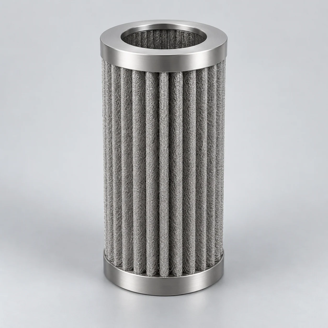
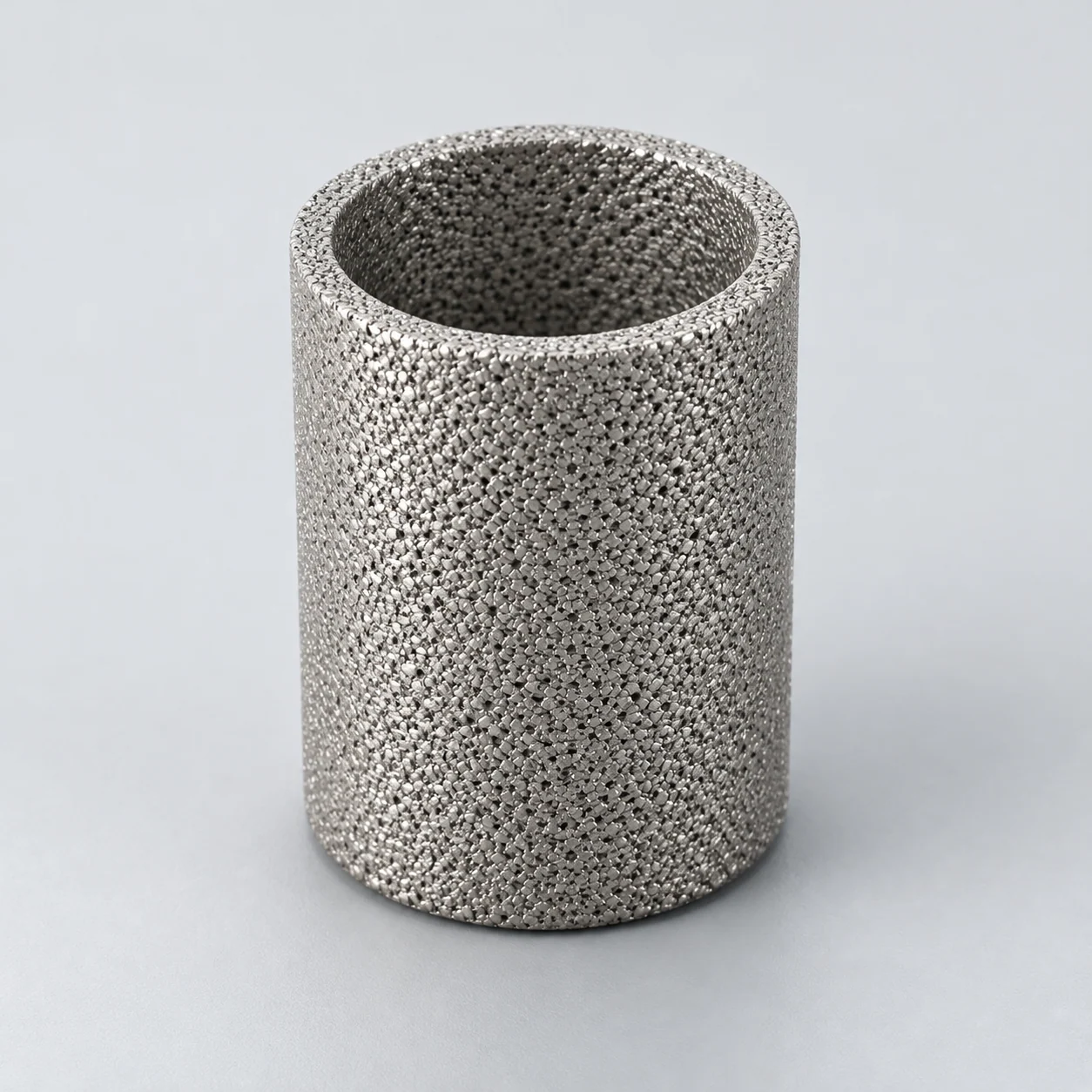
Sintered metal filters for oil & gas and refining

Choose the stream and equipment before comparing the element. FCC slurry-oil crossflow, hydrotreater feed guarding and gas-particle control have different arrangements and acceptance requirements. The three element guides explain those selected applications; analyzer and syngas examples remain in the wider equipment review.

Porous sintered metal powder filter element

Choose the refinery or gas-system element route

Match the equipment and stream first. Use the detailed guide to check the element configuration and its limits before sending a selection or replacement request.

Where the element works in the equipment

Follow the equipment position and separation mechanism, then compare the conditions and evidence needed for selection. These are reference applications, not YUNSHENG installation records.

Backwashable filter vessel on an FCC slurry-oil stream

Element positionOn the main-column-bottom slurry stream of a fluid catalytic cracking unit, before the defined blending, processing or product destination; the solids discharge has its own receiving route.

How the element works

Liquid passes through porous metal elements while catalyst fines accumulate as a retained layer. In a bank designed for inside-out filtration and reverse regeneration, a controlled reverse cycle can dislodge solids for discharge as concentrated slurry. Confirm the flow direction, valve sequence and discharge arrangement against the actual system design. A bare element cannot by itself reproduce the vessel's solids handling or cleaning performance.

Inside-out FCC slurry-oil filter bank

Blue arrows show the inside-out filtration principle: slurry enters the lower dirty chamber, rises through open element bases and crosses the porous walls into the surrounding filtrate space. The separate inset shows reverse cleaning and concentrated-slurry removal after feed and filtrate isolation. These are separate phases of a specific example arrangement, not universal metal-filter directions.

  1. Slurry feed

    Slurry enters the dirty-side distribution chamber below the element support plate.

  2. Inside-out element bank

    The element bases open into the dirty chamber; liquid crosses the walls outward while catalyst fines accumulate on the inner surfaces.

  3. Filtrate space and outlet

    Filtered slurry oil is collected outside the elements and leaves the shell-side outlet.

  4. Separate reverse-cleaning phase

    The inset shows reverse liquid flow from the surrounding clean side into a bore after the normal feed and outlet are isolated. The driving method and valve sequence follow the vessel design.

  5. Concentrated-slurry discharge

    Detached solids leave through the lower dirty-side route during the cleaning/discharge cycle. Destination and containment require a defined process design.

Typical operating conditions

  • Slurry contains suspended catalyst fines in a hydrocarbon liquid; describe the solids distribution and concentration, including changes during unstable operation.
  • Viscosity depends on stream composition and temperature. Include the range relevant to filtration, startup and cleaning, rather than applying an ambient-water flow curve.
  • The vessel cycles between filtration and solids removal. Define forward and reverse differential pressure, available backwash medium, discharge destination and continuity requirements.

Selection decisions

Set the filtrate endpoint
Agree the suspended-solids result and test method required by the downstream use. Distinguish catalyst separation from dissolved-species removal.
Test the feed and cycle
Evaluate media grade, loading and cake release with representative feed where needed. Assess whether early-cycle filtrate needs separate handling.
Review vessel integration
Provide element geometry, supports, joints, alloy specification and the cleaning/discharge sequence. Compare candidate mesh only if capture and release are demonstrated.
Verification and application limits

What to verify

Agree trial acceptance for filtrate quality, pressure-loss development and solids discharge across the operating cycle. Record cleaning effectiveness and checks before returning an element to service.

Application limits

No run length, recovery percentage, filtrate concentration or successful backwash is established for a proposed element by this equipment example.

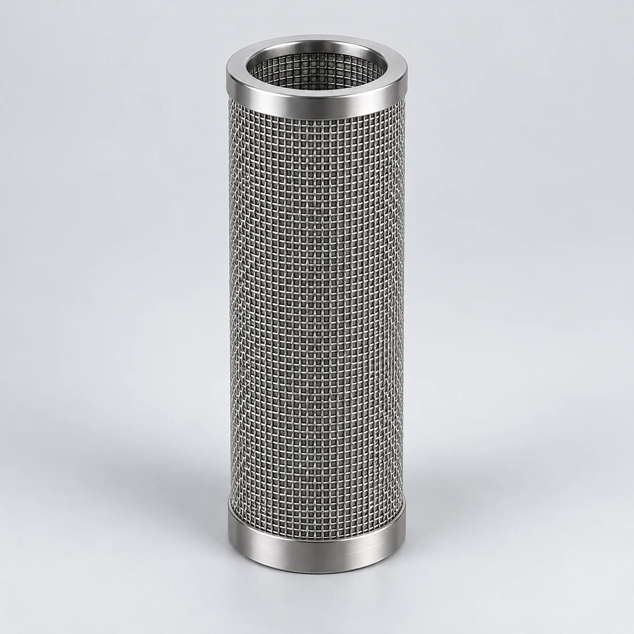
Hydrotreater feed train: backwashable particulate guard filter

Element positionIn the liquid-feed line before the fixed-bed hydroprocessing reactor, at the stage defined by the process design; its position relative to heating and hydrogen addition requires confirmation.

How the element works

A porous-metal barrier removes suspended solids that can contribute to catalyst-bed fouling. The drawing illustrates an inside-out liquid arrangement: feed enters candle bores, filtrate crosses into the shell and retained solids collect internally. A separate reverse wash releases solids toward the bottom discharge. Hydrotreater feed filtration with backwashing is an established industry application; the actual flow direction must be checked against the equipment drawing.

Filter bank before a hydrotreater feed stage

The main view illustrates an inside-out liquid-filtration arrangement ahead of a simplified reactor-feed stage. The separate inset shows a possible reverse-liquid wash and solids drain after isolation. The inside-out flow example illustrates one liquid-process arrangement; the actual hydrotreater system drawing determines its element connections and flow direction.

  1. Liquid-feed inlet

    The feed enters the dirty chamber below the bank. Actual upstream pumps, heating and feed mixing are outside this simplified view.

  2. Porous metal bank

    In the inside-out arrangement shown, liquid crosses from the element bores to the surrounding clean chamber and suspended solids remain upstream of the walls.

  3. Filtered feed to the next stage

    The outlet leads toward a symbolic reactor-feed stage. This is not a hydrotreating process-flow diagram and does not specify the actual plant equipment order.

  4. Separate reverse-liquid wash

    The inset shows compatible clean liquid passing outside-in through an isolated element. The approved vessel cycle determines the cleaning medium, isolation and controls.

  5. Solids drain

    The dirt-laden wash stream follows a separate lower receiving route. Filtration does not remove dissolved metals, sulfur or molecular catalyst poisons.

Typical operating conditions

  • Describe feed origin, particulate distribution and loading, including start-up or tank-change disturbances.
  • Record liquid composition, viscosity and temperature at the proposed filter location; identify any gas phase.
  • State available feed pressure, acceptable operating loss, reverse-cleaning conditions and waste routing.

Selection decisions

Reactor protection
Agree the process-specific particulate acceptance criteria and measurement method. A nominal micron rating does not define catalyst-bed protection.
Feed and cycle trial
Evaluate retention, loading and cake release with representative feed, including initial filtrate after cleaning and any necessary recycle.
Project integration
Review alloy, supports, seals, valve sequence and safe isolation. Separate vessel pressure from the element's forward and reverse differential-pressure limits.
Verification and application limits

What to verify

Agree an acceptance plan covering filtrate solids, throughput, pressure-drop development, backwash recovery and interface integrity over repeated cycles.

Application limits

A particulate filter does not remove dissolved sulfur or prove catalyst life extension. Sour-service suitability, vessel compliance and the proposed element ratings require separate evidence.

Particulate filter ahead of a gas pressure regulator

Element positionUpstream of a regulator or critical control valve in a process-gas or instrumentation package, where the package designer specifies particle protection and maintenance access.

How the element works

A porous sintered element or a verified mesh construction intercepts solids before they reach the regulator seat and small passages. Upstream particulate filtration is a common way to reduce regulator seat contamination. The filter and regulator form a pressure-loss chain: protecting the seat must be balanced against supplying the required inlet pressure at peak demand.

Typical operating conditions

  • Commissioning debris, corrosion products or other solids may enter with the gas; describe loading during startup separately from normal service.
  • Give composition, moisture and possible liquid carryover. Identify hydrogen sulfide, carbon dioxide and other relevant species without assuming that a familiar alloy is suitable.
  • State gas flow reference conditions, minimum and maximum inlet pressure, temperature and the pressure available at the regulator during maximum demand.

Selection decisions

Define the protection target
Obtain the downstream component's particle requirement. Compare retention evidence and bypass prevention, not merely pore size or nominal micron rating.
Budget pressure loss
Separate assembly working pressure, allowed operating pressure loss and element differential-pressure strength. Include a loaded element and startup transients in the review.
Assess the complete wetted set
Review element, joints, seals and housing against composition and temperature. Confirm installation direction and a safe maintenance/isolation arrangement with the package designer.
Verification and application limits

What to verify

Agree gas-flow and pressure-loss evidence at defined reference conditions, relevant retention tests and interface checks. Keep required material and inspection documents attached to the exact proposed construction.

Application limits

Solid capture does not establish liquid coalescence, vapor removal, sour-service suitability or hazardous-area approval. Filtration does not replace downstream overpressure protection.

Replaceable particle element in an analyzer field station

Element positionAt the sample extraction point in a refinery or gas-processing analytical system, typically within the conditioning package before the long transport line to the analyzer.

How the element works

The field station combines sample conditioning with pressure reduction near extraction. A metal particle element can retain solids before sensitive components; the selected filter location must follow the package drawing. Particulate filtration, membrane separation and coalescing are distinct functions with distinct components. These functions cannot be collapsed into a single metal-pore specification, especially when liquid mist or phase changes affect sample composition.

Typical operating conditions

  • State the measured species, required phase and sample pressure at extraction, including condensable hydrocarbons, water and particulate loading.
  • Describe pressure reduction, heat loss and the temperature profile through the filter, regulator and transport line; assess possible condensation with the sample-system designer.
  • Sample flow and internal volume affect transport and response. Include flow reference conditions, line length and the existing filter's service history or failure symptoms.

Selection decisions

Preserve analytical information
Define what may be removed without biasing the measurement. Evaluate interaction with surfaces and liquid formation, not just whether the sample looks clean.
Identify the original function
Confirm whether the installed part is a particle filter, coalescer or membrane separator. A sintered metal replacement must not silently change that function.
Match the approved interfaces
Obtain the current drawing and specification revision. Review seals, dimensions, flow direction, pressure loss and retention evidence for the exact proposed part.
Verification and application limits

What to verify

Check sample response and composition through the complete system alongside retention, flow and leak/interface acceptance. Keep component test evidence separate from equipment-level analytical validation.

Application limits

A replacement element does not inherit the original field station's approvals, sample representativeness or pressure-temperature ratings. Particle filtration alone does not remove vapor.

Refinery gasification train: syngas char-filter vessel

Element positionIn the hot-syngas cleanup train after gasification and the designed upstream heat/solids-handling stages, before downstream equipment requiring a lower particulate burden.

How the element works

Metallic barrier elements separate entrained char from the gas. A surface cake develops and contributes to pressure loss; controlled reverse pulses release deposits for collection and discharge. Inlet distribution, element assemblies and pulse equipment must be evaluated as one system. The actual vessel drawing determines the filtration direction, pulse grouping and solids route; those cannot be inferred from the medium name.

Typical operating conditions

  • Define syngas composition, pressure and temperature, including corrosive species, water and condensable constituents.
  • State actual flow and reference conditions for standardised volumes; describe char loading and abrasiveness.
  • Include thermal transitions, cleaning-gas composition and pressure, discharge conditions and availability requirements.

Selection decisions

Corrosion and strength
Request evidence for the proposed porous alloy, joints and supports under the complete atmosphere and cyclic application; familiar stainless steel is not automatic qualification.
Gas distribution
Review inlet distribution, accessible filtration area, cake spacing and outlet acceptance with the vessel designer.
Regeneration and solids
Assess release of representative char, reverse differential pressure and the solids-discharge sequence. More elements alone cannot compensate for poor distribution or ineffective cleaning.
Verification and application limits

What to verify

Agree representative-feed and, where justified, pilot evaluation of particulate carryover, cycle stability, cleaning recovery and post-exposure material condition.

Application limits

Char capture does not establish removal of gas-phase contaminants, tar conversion, sulfur treatment or fuel-gas compliance. Specialized alloy or coating claims cannot be transferred between different component configurations.

A selection sequence for this industry

  1. Separate the contaminant phases

    Specify solid particles, liquid droplets and vapor independently. Decide which phase must remain in an analytical sample and which must be removed from a process stream.

  2. Define the full pressure and cycle envelope

    Record line pressure, temperature, flow basis and allowed differential pressure independently. Include low-inlet-pressure gas demand, slurry backwash or sample depressurisation as applicable.

  3. Agree project-specific evidence

    Select candidates against retention, compatibility, drawings and a verification plan. Sour-service requirements, housing design and assembly approvals need their own documented review.

Define the operating envelope

Use actual process conditions, including start-up, shutdown and cleaning. A normal operating point does not describe every load on the element.

Composition and phase
Gas or liquid analysis, water content and relevant contaminants, including H₂S or CO₂ where present.
Flow basis
Normal, minimum and maximum flow; for gas, state whether volume is actual or referenced and give the reference conditions.
Mechanical loading
Operating pressure, vacuum, forward and reverse differential pressure, and pressure or temperature transients.
Assembly and site requirements
Housing interfaces, materials, sealing, inspection records and any project-specific equipment requirements.

Define acceptance before selecting a solution

Separate particulate and droplet objectives

If liquid carryover must be controlled, review coalescence, drainage and re-entrainment as a distinct function rather than assuming a solids filter will meet it.

Review corrosive constituents together

Where hydrogen sulfide and water are present, exposure assessment also considers pressure, temperature, pH and other constituents. A generic stainless-steel description is insufficient.

Agree the assembled-element checks

Use a drawing, material record, defined flow test and integrity assessment linked to the complete element. State the test direction and conditions.

Prepare the refinery and gas-system selection basis

Keep flow conditions, particle acceptance and materials evidence distinct when assembling a comparable inquiry.

Questions before selection

Can the housing pressure rating be used as the element differential-pressure rating?

No. The housing boundary and porous element carry different loads. Obtain the element’s permitted forward and reverse differential pressure for its actual support and temperature conditions.

Why do gas-flow reference conditions matter?

The same mass flow occupies different volumes at different pressure and temperature. Reference conditions are needed to convert the stated flow into the operating conditions.

Is a particulate element also a flame arrester?

No. Flame arresting is a separate safety function requiring a purpose-specific design and qualification. It cannot be inferred from the presence of porous metal.

Discuss the element within the refinery or gas system

Identify the actual stream, equipment and separation target. Add the drawing and service conditions you have so the request follows the intended flow arrangement.

Inquiry contextSintered metal filters for oil & gas and refining

Useful if available — optional for your first inquiry:

  • Equipment and actual stream: FCC slurry oil, hydrotreater feed, process gas or another defined application.
  • Contaminant description, required outlet condition, operating temperature, pressure and flow basis if known.
  • Available element or housing drawing, selected flow arrangement, cleaning cycle and project-specific material or inspection requirements.
Request a quote

Use the full inquiry form to attach a drawing or file. The short form alongside accepts your message.

Regarding: Sintered metal filters for oil & gas and refining

Send a message

* Required. For drawings and operating conditions, use the full inquiry form. Open technical inquiry

Continue in this tab. Your entered contact details and message are transferred once; consent must be given again.

Name & company · optional
Privacy information — read here

Your contact details and requirements are used to respond to your inquiry.

Opening privacy information keeps this form in its original tab. Files must be selected again after a reload.

Privacy information