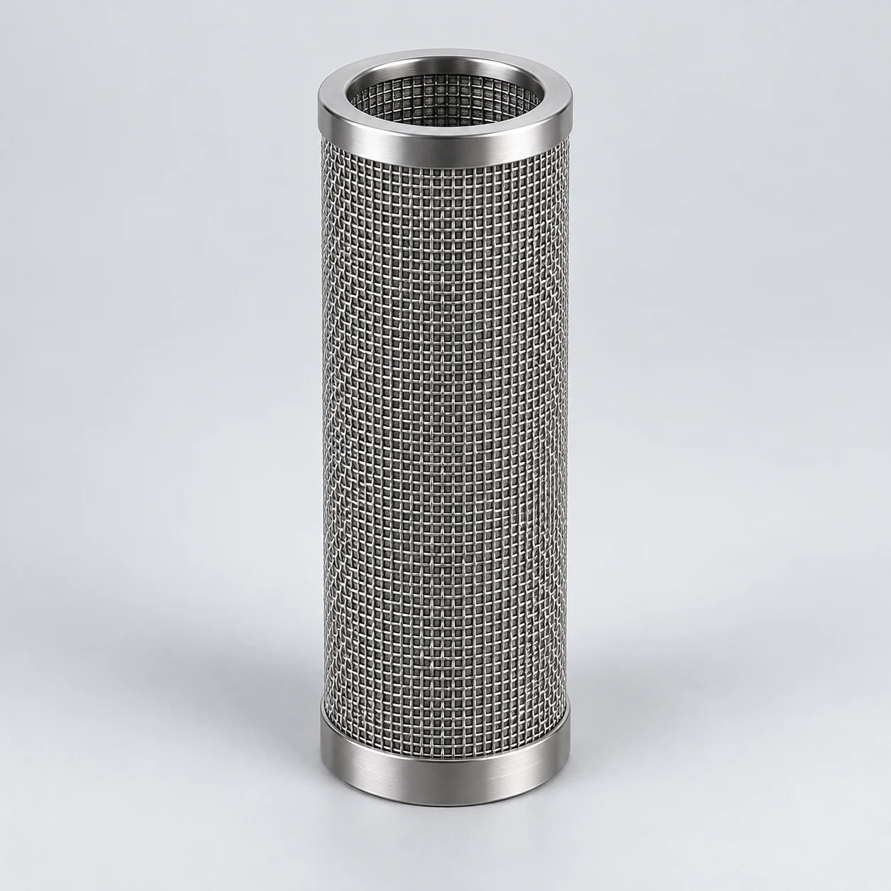
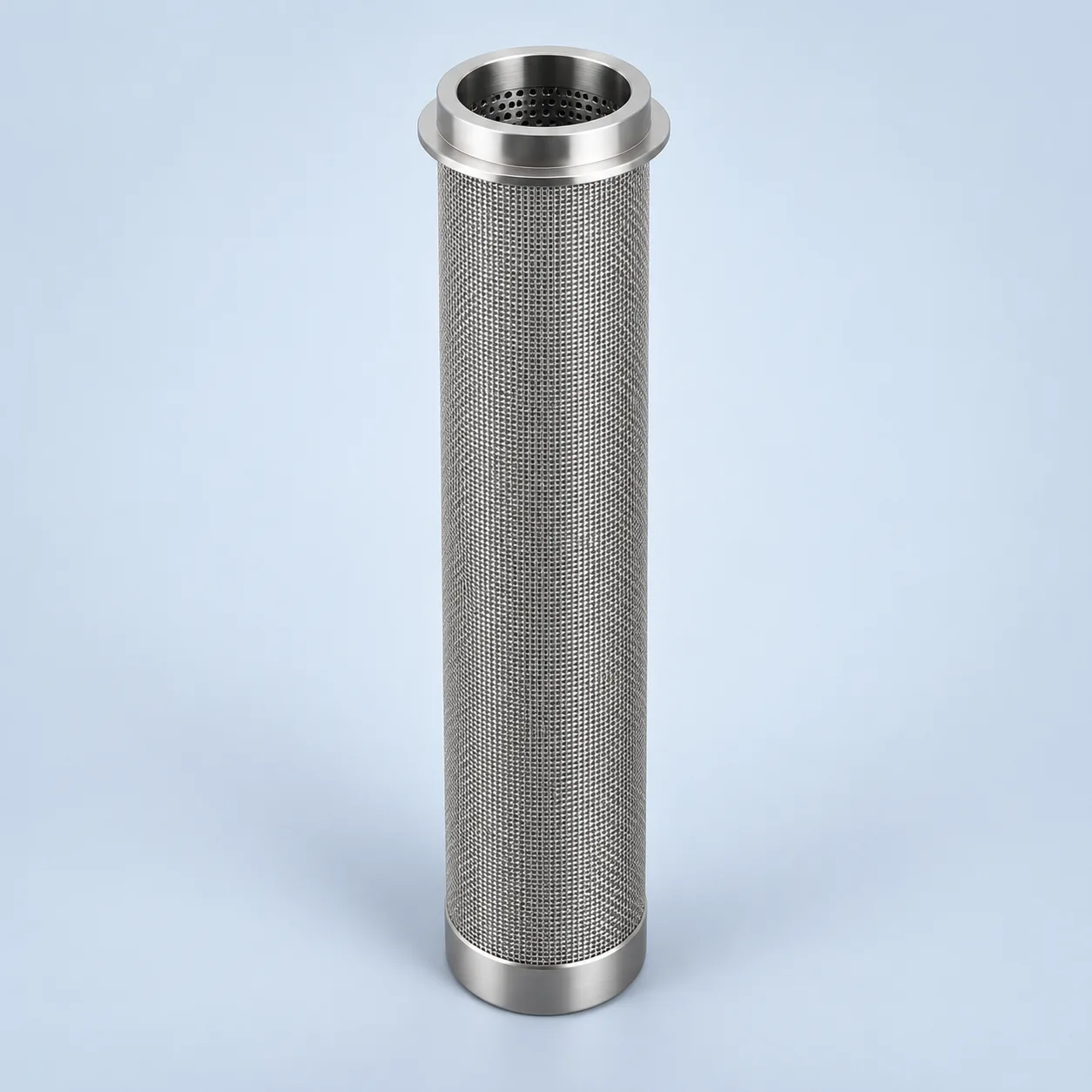
Start with the feed application and installed drawing. Confirm material compatibility, retention, forward/reverse differential-pressure limits and cleaning acceptance for the proposed assembly.
Feed-guard mesh cartridge — section

- Filtering wall
The feed-guard section distinguishes mesh media from its support. Confirm the actual solids, mesh construction and forward/reverse load limits.
- Connection and seal
The open cartridge end seals into the filtered-feed collector, preventing untreated liquid feed from bypassing the mesh.
- Clean central passage
In this selected outside-in layout, filtered liquid feed travels through the bore to the clean collector and downstream equipment.
- Closed lower end
The illustrated lower end is closed so liquid feed crosses the mesh. Confirm the end construction and cleaning route against the installed filter drawing.
Feed guard — before downstream processing
The selected outside-in cartridge bank removes specified suspended particles before downstream processing. Each element opens into a sealed clean collector. The downstream block is equipment context, not a catalyst bed drawing or a statement of the filter position relative to every pump or heater. Plant design defines those positions and any cleaning, bypass or drain circuit.

- Feed-filter housing
The housing is on the liquid feed line. Its actual position follows the plant process design.
- Supported mesh bank
In this illustrated direction, solids remain outside the mesh and liquid enters the central passages.
- Clean-side collector and seals
The tube sheet and mounting seals prevent unfiltered feed from bypassing into the outlet.
- Downstream equipment
Particle removal can protect selected downstream components. The drawing does not imply dissolved-sulfur removal or water coalescence.
Define the guard stage on the refinery flowsheet
A hydrotreater feed guard filter removes specified suspended solids before sensitive downstream equipment and the catalyst bed. Cartridge retention and a backwash arrangement require different maintenance provisions. Solids removal must also be distinguished from water coalescence. The exact filter location relative to pumps, heating and mixing must follow the plant process design.
Use the operating feed description, not the reactor's maximum conditions, as the filter sizing basis. Confirm the installed housing, element manifold, bypass arrangement and cleaning-discharge route.
Match the medium to the contamination mechanism
A supported mesh element can be evaluated for retaining scale, rust and other particulate while liquid passes to a clean collector. Surface loading may allow deposit removal by reverse flow when the contaminant and system design permit it. Confirm filtration direction and both pressure-load directions on the element drawing.
Soft deposits and semi-solids can behave differently from hard particles. Characterize asphaltene-related fouling, gums or mixed deposits before selecting a reusable screen. Particle filtration does not remove dissolved sulfur and is not a substitute for a water coalescer.
Feed-guard specification schedule
On a small screen, scroll the table sideways to see every column.
| Parameter | Unit or evidence | Selection and acceptance basis |
|---|---|---|
| Feed composition and state | Stream analysis; viscosity versus temperature | Include water, gas, additives and relevant corrosive species. |
| Solids and fouling | mg/L; particle distribution; deposit description | Distinguish hard debris from sticky or deformable contamination. |
| Downstream protection target | Residual solids; efficiency; test method | Agree the actual catalyst/equipment protection requirement. |
| Flow envelope | m³/h; temperature; pressure | Normal, turndown, startup and upset at the guard-filter location. |
| Element resistance and strength | bar with test conditions | Separate clean loss, terminal forward load and reverse cleaning load. |
| Backwash and disposal | Fluid; available pressure; drain route | Check cleaning recovery, contamination handling and plant interlocks. |
| Fit and traceability | Controlled drawing; material/test records | Verify seating, seals, supports, welds and inspection scope. |
Specify an alloy by the actual exposure
Review 316L or a higher-alloy alternative against feed contaminants, water phase, temperature and cleaning exposure. A specifically identified nickel-chromium-molybdenum grade may warrant evaluation for certain aggressive conditions; it still needs compatible supports, welded fittings and documented material condition.
For wet-H₂S service, specify the governing refinery-project material requirements and obtain evidence for the exact porous material, supports, joints and fabrication condition. A generic stainless or nickel-alloy designation does not establish suitability or qualify the filter housing; the applicable standard and acceptance scope must be agreed for the actual operating conditions.
Agree the operating evidence before a replacement campaign
Request element-specific flow and retention data, forward/reverse pressure verification, material traceability and an approved regeneration procedure. If the deposit is uncertain, use an agreed feed sample assessment or limited monitored trial before a full replacement.
Track differential-pressure rise, treated volume, cleaning recovery and downstream solids on the same feed basis. Request identified deviations rather than fill missing fields with catalog maxima. A successful registration of a cleaning cycle is not a demonstrated restoration of filtration performance.
- Provide the original drawing and current failure symptoms.
- Include a pressure trend, contamination sample information and cleaning sequence.
- Separate expected operating benefit from performance already demonstrated.
Specification and acceptance checks
Review the guard bank against the downstream protection target and actual deposit type. Confirm end connections, supports and cleaning conditions for this outside-in configuration; a similarly sized mesh cartridge is not automatically interchangeable.
On a small screen, scroll the table sideways to see every column.
| Check | Specify | Acceptance record |
|---|---|---|
| Feed and deposit | Composition, viscosity and hard/sticky contamination | Feed analysis and deposit description |
| Protection target | Residual solids and agreed retention method | Acceptance tied to downstream tolerance |
| Fit and loading | Seat, seals, supports and temperature-specific differential pressure | Element/bank drawings and load records |
| Regeneration | Permitted reverse load and disposal route | Recovery and post-cleaning integrity check |
- Keep housing operating pressure separate from forward and reverse element limits.
- Particle filtration does not replace water coalescing or remove dissolved sulfur.
Prepare the specification for this application
Use these guides to resolve the next selection questions for this element. Each covers a separate part of the specification.
Product family: Sintered wire mesh filter elements
- Sintered filter micron rating: what it does and does not tell you
Tie guard-stage retention to the actual feed solids and a defined test.
- Sintered metal filter pressure drop and flow area
Allocate clean and loaded pressure loss before the downstream process unit.
- How to clean sintered metal filters safely
Assess deposit removal, support integrity and reuse checks for the guard element.