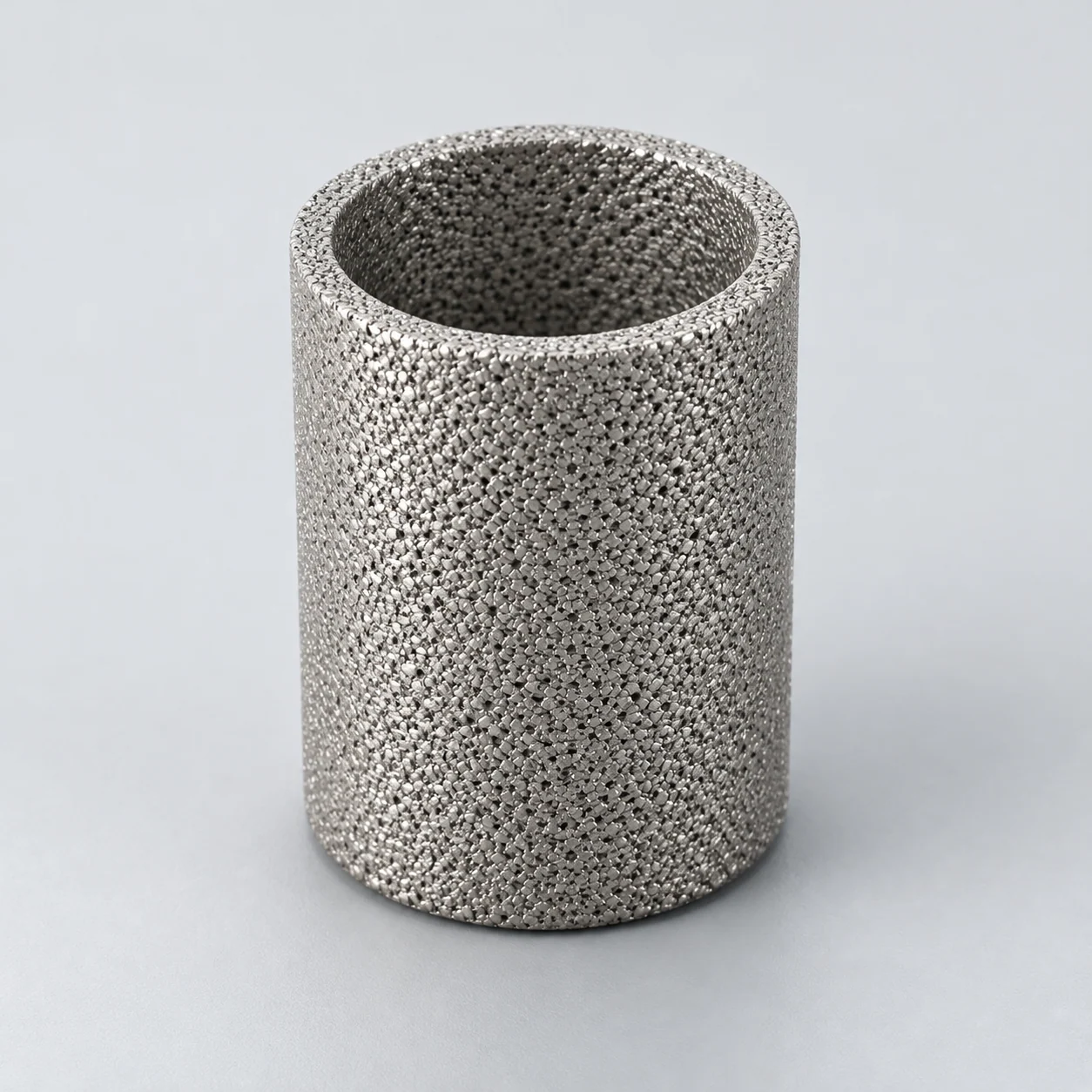
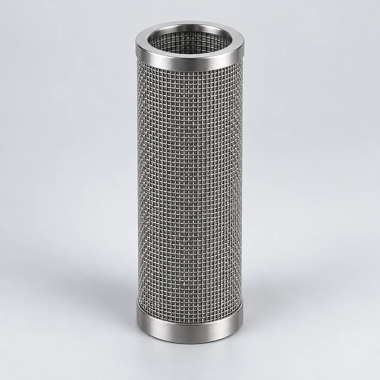
Sintered metal filters for general industrial processes

Separate the water circuit, hot-gas vessel and analyzer sample branch before selecting a metal element. Each has a different flow basis, loading pattern and maintenance application. The element guides provide the next step for these three applications; nozzle-line and hydraulic examples remain in the equipment review below.

Cylindrical sintered wire mesh filter element

Start with the industrial equipment application

Choose the matching element guide for a closer installation and flow review. If you are replacing a different component, use the equipment examples below and include the original interface.

Where the element works in the equipment

Follow the equipment position and separation mechanism, then compare the conditions and evidence needed for selection. These are reference applications, not YUNSHENG installation records.

Central cooling/process-water station: multi-candle backwash filter

Element positionIn the selected full-flow or side-stream water circuit, before the protected distribution system or heat-transfer equipment; the plant designer defines pump and isolation positions.

How the element works

Parallel metallic candles provide filtration area within one housing. In the double-open-ended example, water enters the candle interiors and crosses the wall inside-out. Selected-candle backflushing uses reverse flow and an axial sweep to discharge retained solids while the other candles remain in filtration. The cleaning manifold is part of the system, not a property of the mesh alone.

Double-open element bank in a water backwash filter

The main view shows filtration only: feed reaches both open ends of the candles, passes inside-out through the walls and leaves from the surrounding filtrate space. The separate right-hand inset shows a selected candle during backflushing: axial sweep and reverse wall flow carry solids toward its lower drain. The inset is a different phase, not a simultaneous flow path in that candle.

  1. Feed distribution

    The lower dirty chamber supplies the bottom openings and a riser supplies the upper openings. The drawing simplifies the distributor.

  2. Double-open candles

    During filtration, water travels from the bores through the metal walls into the surrounding clean chamber. Both ends are open.

  3. Filtrate outlet

    The clean surrounding chamber collects the filtered water and supplies the outlet.

  4. Selected backflush phase

    In the separate inset, a control arrangement restricts the top and connects the lower bore to discharge; axial sweep and outside-in flow assist removal. Exact controls are equipment-specific.

  5. Solids discharge

    The selected bore discharges the dirt-laden wash stream through a controlled route. This is not an uncontrolled bypass from the normal dirty chamber.

Typical operating conditions

  • Record seasonal water quality, suspended particles, fibers and any biological fouling separately.
  • State full-flow versus side-stream application, peak liquid flow and available pressure at the filter inlet.
  • Include backflush water availability, drain backpressure and the receiving route for solids.

Selection decisions

Retention objective
Start with the protected equipment's tolerance. Screen aperture and a tested particle-removal rating are different specifications.
Construction and cleaning
Check openings, supports, seals and the flushing selector. A proposed sintered-mesh design needs compatibility review against the original woven-mesh or wedge-wire construction.
Area and pressure budget
Size effective area from liquid trials and loading. Separate housing pressure, clean/dirty operating loss and forward/reverse element differential-pressure limits.
Verification and application limits

What to verify

Agree retention, pressure-drop recovery and solids-discharge checks over representative dirty-water cycles, including the downstream flow during cleaning.

Application limits

Particle screening does not remove dissolved salts or establish microbiological control. OEM interchangeability and the economic choice of metal medium are confirmed for each project.

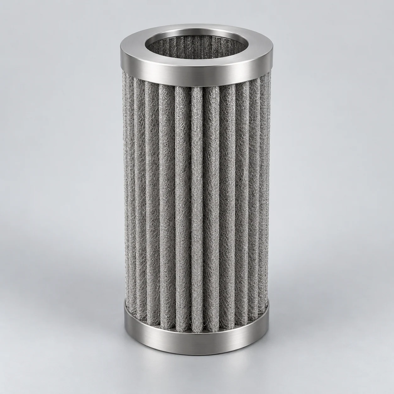
Calciner or thermal-process exhaust: metallic hot-gas filter vessel

Element positionIn the equipment owner's defined hot-gas cleaning train, after the calcining or thermal operation and before the next protected process stage or further gas treatment.

How the element works

Porous metallic elements retain entrained process dust; a deposited cake adds separation resistance and pressure loss. For the outside-in plenum arrangement shown, gas crosses into the candle bores and leaves through the clean plenum. Feed is isolated for a separate reverse-gas cycle that releases surface dust into the hopper. Other systems use different cleaning sequences; metal-fiber use in calcining is documented separately.

Hot-gas element bank with a clean upper plenum

The main view illustrates outside-in filtration into an upper clean plenum. The separate right-hand inset shows reverse cleaning with feed discontinued; the compatible cleaning gas crosses the wall in the opposite direction and dust falls. This generic plenum-cleaned arrangement is not an exact diagram of a manufacturer installation and does not imply online cleaning.

  1. Dust-laden gas inlet

    Gas enters the lower dirty chamber. Actual inlet distribution and protection from direct impingement require equipment design.

  2. Hanging metal elements

    Gas crosses the walls from outside to inside in this example. The upper tubeplate and sealed connections separate dirty gas from the clean plenum.

  3. Clean plenum and gas outlet

    Filtered gas rises through the element bores and leaves the upper chamber.

  4. Separate reverse-cleaning phase

    The inset illustrates clean compatible gas entering an isolated clean side and flowing inside-out. Normal feed is discontinued in the plenum-cleaned example.

  5. Dust collection and discharge

    Released dust drops toward the hopper; the actual discharge, isolation and dust-hazard controls are not specified by this diagram.

Typical operating conditions

  • Specify actual gas flow, temperature, pressure and reference conditions for any normalized flow.
  • Describe atmosphere, vapors, moisture and dust chemistry, including start-up and shutdown exposure.
  • Record dust loading, agglomeration or stickiness, thermal cycling and the available cleaning-gas supply.

Selection decisions

Media and alloy
Compare candidate fiber or powder structures using retention, permeability and atmosphere-specific durability evidence; an alloy name alone is insufficient.
Surface and release
Evaluate cake formation, spacing and dust removal. Extra pleated area is useful only if the gas and cleaning pulse can reach it.
Complete vessel
Review tubeplate seals, expansion allowance, hopper discharge and normal/reverse differential pressure with the equipment designer.
Verification and application limits

What to verify

Agree representative-dust testing and, where needed, hot-gas trials covering outlet particles, pressure-loss trend, cleaning recovery and material condition.

Application limits

No emission compliance, universal hot-gas rating or service life is implied. The drawing shows a functional example rather than a specific installation.

T-strainer in a spray-nozzle supply line

Element positionIn the liquid feed to a spray header or tank-cleaning nozzle, at the position specified by the equipment designer and with access to remove the screen.

How the element works

A mesh barrier intercepts suspended debris before it reaches small nozzle passages. Removable wire-mesh screens in T-strainers are a common nozzle-protection arrangement. A sintered mesh laminate is not needed in every nozzle system. Consider a supported or sintered mesh construction only when the required retention, support or cleaning conditions justify it.

Typical operating conditions

  • Recirculated wash water or process liquid can carry rust, scale and debris released during maintenance; establish the actual contaminant distribution.
  • Record the liquid's viscosity and temperature and the simultaneous demand from the operating nozzles, rather than sizing from a connection diameter alone.
  • Loading raises pressure loss and may reduce pressure available at the nozzle; describe the cleaning interval, isolation arrangement and disposal of retained material.

Selection decisions

Work back from the nozzle
Obtain the nozzle manufacturer's acceptable particle size and pressure requirement. A mesh count without wire diameter or opening data is incomplete.
Preserve the flow budget
Compare open filtration area, supports and housing loss at the intended flow. Keep system working pressure separate from element differential pressure.
Choose a maintainable construction
Check screen access, sealing, flow direction and cleaning compatibility against the drawing. Avoid adding fine retention without a downstream reason.
Verification and application limits

What to verify

Agree a clean-assembly pressure-loss check and retention evidence relevant to the debris. After cleaning, inspect the screen and sealing surfaces; restored flow alone does not prove that an opening or joint remains intact.

Application limits

This is suspended-particle screening. It does not remove dissolved salts, correct water chemistry or establish emulsion separation.

Porous sampling tube in a CEMS gas-sampling assembly

Element positionIn a stack-mounted or external sample-extraction assembly ahead of an emissions analyzer; the filtered sample is a side stream from the main gas path.

How the element works

In a suitably designed inertial sampling assembly, gas and most entrained particles travel axially along a porous tube while a smaller sample passes through its wall. When the flow arrangement maintains this cross-flow, it can carry much of the dust onward and reduce deposition compared with forcing the whole dusty stream through the medium. This behavior requires verification for the complete assembly and actual flow conditions; it is not a self-cleaning claim for a stand-alone sintered tube.

Typical operating conditions

  • Combustion or process exhaust may contain dust, moisture and condensable compounds; record what the analyzer must actually measure.
  • Describe the gas temperature along the extraction and transport path, dew-point risks and both the axial and extracted sample flows with their reference conditions.
  • Low available pressure or variable stack flow may require a separately designed flow-driving arrangement; include the return path, sampling-line length and analyzer demand.

Selection decisions

Define the measurement
Identify target species and the required response time. Assess adsorption, condensation and other changes in composition with the analyzer-system designer.
Separate the two flows
State axial bypass flow and trans-wall sample flow separately. Review porous area, permeability and sample pressure loss together.
Review the assembly
Supply the probe drawing, dust characteristics, cleaning method, seals and alloy exposure. A pore label alone does not specify an inertial sampling system.
Verification and application limits

What to verify

Evaluate sample response and composition against the agreed sampling method, as well as particle capture and flow stability. Confirm cleaning and reassembly checks for the actual assembly.

Application limits

A particle-filter component does not establish CEMS compliance, remove every aerosol or guarantee representative sampling.

Metal-fiber cartridge in a hydraulic power-unit circuit

Element positionInside the filter housing identified on the hydraulic diagram, for example a pressure-line or return-line assembly protecting valves and actuators. These locations are not interchangeable.

How the element works

A porous metal-fiber network can capture particles through its depth; pleating can add usable media area within a cartridge envelope. Effective filtration also depends on the support, seals and flow distribution in the complete cartridge. Assess retention, pressure loss, load capacity and circuit position for the proposed assembly; this construction does not establish suitability as a replacement for any existing paper or glass-fiber element.

Typical operating conditions

  • Hydraulic oil viscosity changes with temperature; include cold starting, normal operation and the actual fluid formulation.
  • Valve movements and pump operation may produce pulsating flow and pressure. State peak flow, flow direction and element differential-pressure exposure separately from line pressure.
  • Existing bypass valves and clogging indicators affect filtration during loading and cold operation; retain the equipment designer's intended control strategy.

Selection decisions

Use a cleanliness target
Obtain the equipment's required cleanliness and applicable efficiency test. A common nominal micron number is not replacement evidence.
Match function and fit
Compare seals, support, dimensions, collapse requirements, flow direction and bypass arrangement with the original drawing and specification.
Check the viscous case
Review pressure loss at the relevant flow and viscosity. Assess loading capacity and maintenance access before choosing pleat geometry or finer media.
Verification and application limits

What to verify

Use agreed retention or efficiency evidence and hydraulic checks appropriate to the assembly. Confirm oil cleanliness separately by the agreed sampling method; a differential-pressure indicator is not a particle counter.

Application limits

External fit, a stainless steel label or restored flow after cleaning does not prove equivalent hydraulic protection. Reuse needs an accepted cleaning and requalification method.

A selection sequence for this industry

  1. Identify the protected function

    A nozzle passage, an analytical measurement and a hydraulic valve have different failure criteria. Start with the equipment requirement and contaminant, then shortlist the medium.

  2. Compare under the real operating cycle

    Review fluid properties, flow range and clean/loaded differential pressure. Include cold starts, transients and any reverse cleaning flow rather than choosing from a single nominal point.

  3. Make replacement evidence explicit

    Request the drawing, retention basis and acceptance method. Assess both the element and its interfaces; match outer dimensions only after functional requirements are understood.

Define the operating envelope

Use actual process conditions, including start-up, shutdown and cleaning. A normal operating point does not describe every load on the element.

Equipment requirement
Protected part, failure mode and the equipment maker’s relevant filtration specification.
Fluid and contamination
Fluid identity, viscosity, chemistry, particle type and normal or abnormal contamination loading.
Mechanical interface
Overall dimensions, seals, adapters, flow direction and housing installation space.
Service history
Clean and loaded differential pressure, typical service interval and observations from removed elements.

Define acceptance before selecting a solution

Check fit before comparing service life

Confirm sealing and support first. A bypass path can create an apparently low pressure drop while reducing particle control.

Compare the same operating conditions

When evaluating alternatives, keep fluid temperature, flow, contamination and measurement location consistent.

Use a practical maintenance record

Log installation, differential-pressure trend, cleaning and inspection results against an element identifier. This gives later changes a reliable comparison point.

Define industrial flow and maintenance requirements

Use the relevant flow basis for each medium, then agree how the loaded or cleaned element will be evaluated.

Questions before selection

Can the same element treat compressed-air particles and oil mist?

These are different separation tasks. A particulate element does not automatically provide coalescing, drainage or oil-vapor removal; define each required contaminant target.

Does low pressure drop prove good filtration?

No. It indicates hydraulic behavior at the measured condition. Retention, seal integrity and the absence of bypass need separate evidence.

How can a replacement inquiry be made more precise?

Include a drawing or measured interfaces, fluid and flow data, original rating information and photographs of the removed element. State what should improve and what must stay compatible.

Start an inquiry from the industrial application

You can start with the equipment or an existing element. Send the flow and installation information you know; unmeasured operating values can be clarified later.

Inquiry contextSintered metal filters for general industrial processes

Useful if available — optional for your first inquiry:

  • Equipment and application: water circuit, hot-gas vessel, sample branch, nozzle line or hydraulic circuit.
  • Medium, solids, operating temperature and flow basis; identify the reference conditions for gas flow.
  • Available drawing or replacement dimensions, flow direction and the proposed cleaning or backwash cycle.
Request a quote

Use the full inquiry form to attach a drawing or file. The short form alongside accepts your message.

Regarding: Sintered metal filters for general industrial processes

Send a message

* Required. For drawings and operating conditions, use the full inquiry form. Open technical inquiry

Continue in this tab. Your entered contact details and message are transferred once; consent must be given again.

Name & company · optional
Privacy information — read here

Your contact details and requirements are used to respond to your inquiry.

Opening privacy information keeps this form in its original tab. Files must be selected again after a reload.

Privacy information