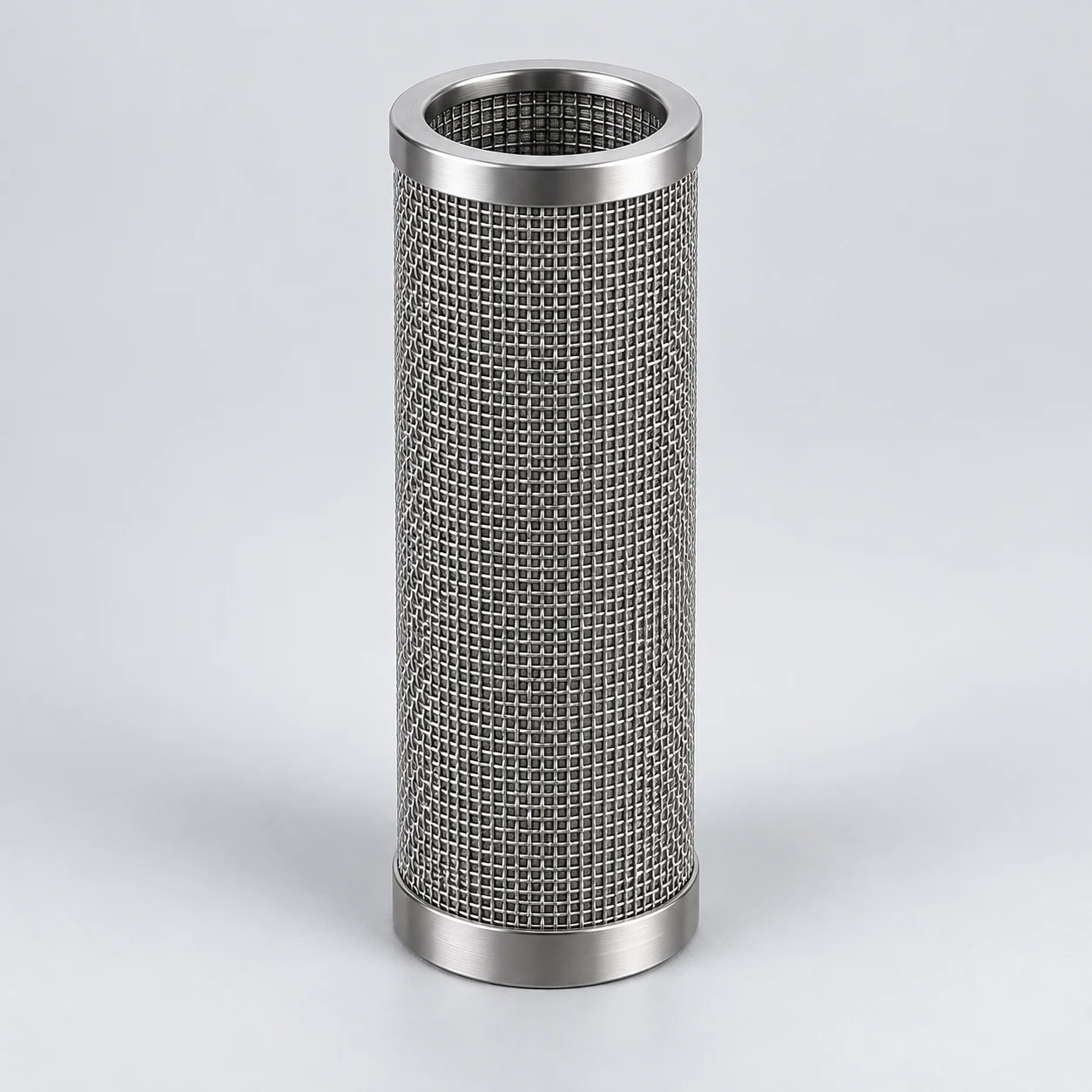
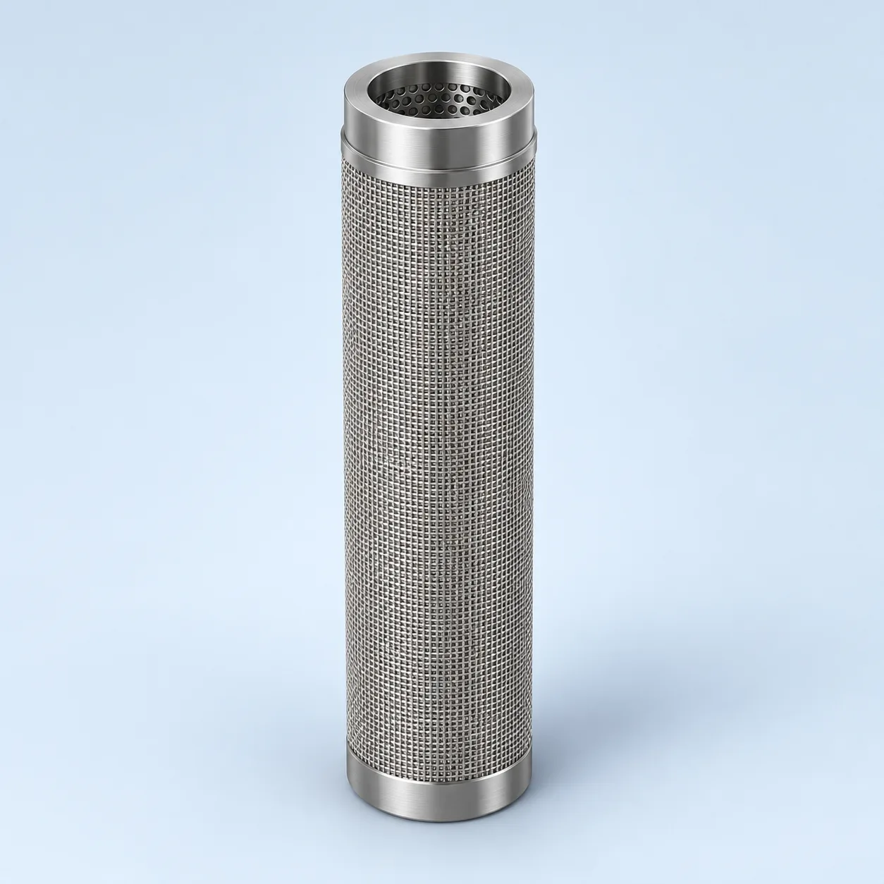
General screening and hydraulic-cleaning guidance. System configuration, industrial suitability, flow capacity and cleaning performance require project-specific confirmation.
Supported mesh screen — section

- Filtering wall
The water-screen section distinguishes mesh media from its support. Layer count, support geometry and forward/reverse loading require confirmation.
- Connection and seal
The open water-screen end is sealed into the clean collector so raw water cannot bypass the mesh.
- Clean central passage
In this selected outside-in layout, filtered water travels along the bore to the clean collector and outlet.
- Closed lower end
The illustrated closed end prevents raw water from entering the bore axially. Confirm this end arrangement against the installed screen.
Water filter — filtration and isolated cleaning
Selected example: liquid crosses a supported mesh candle from outside to inside and leaves through a sealed clean plenum. The separate right-hand state isolates the bank and sends clean water in reverse through the wall to a dirty discharge. Scanning-nozzle cleaning is a different arrangement and is not shown.

Selected example: liquid crosses a supported mesh candle from outside to inside and leaves through a sealed clean plenum. The separate right-hand state isolates the bank and sends clean water in reverse through the wall to a dirty discharge. Scanning-nozzle cleaning is a different arrangement and is not shown.
- Dirty-water chamber
Feed remains outside the mesh; the housing and supports must suit the agreed forward and reverse loading.
- Mesh candle and support
The illustrated closed-end candle opens only to the clean plenum through its mounting seal.
- Clean collection
Liquid that crosses the mesh enters the bore, then the clean plenum and outlet.
- Isolated cleaning state
Dashed arrows belong only to the separate reverse-cleaning state. Supply isolation, valves and the discharge route require a system drawing.
Product images
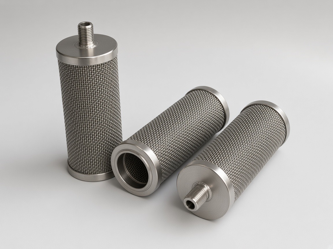
Identify the screen and its cleaning mechanism
A central-water filter may use a cylindrical screen separating the dirty-water chamber from the clean outlet. Some designs clean a small screen area through a scanning suction nozzle; others isolate a bank and reverse flow through it. Specify the actual mechanism because screen supports and pressure loading differ.
Hydraulic scanning and reverse-flow cleaning use a local pressure difference to remove retained solids from the screen. The cleaning arrangement must match the screen construction, available discharge pressure and solids load. Cooling, wash-water and process-water circuits need separate hydraulic and water-quality assessments.
Backwash requires a usable pressure difference
During filtration, water crosses the screen and suspended solids accumulate on its dirty face. During cleaning, the local or bank-wide flow reverses to lift deposits into a drain stream. The effective cleaning force depends on the clean-side pressure, drain pressure, valve/nozzle losses and screen resistance.
A controller command is not evidence that cleaning occurred. Record the pressure recovery and solids discharge. If biofilm, oil, fibrous debris or scale binds to the surface, a water-only backwash may be inadequate even when loose mineral particles discharge readily.
Technical inputs for water and backwash
On a small screen, scroll the table sideways to see every column.
| Parameter | Unit or evidence | Required distinction |
|---|---|---|
| Water flow | m³/h at stated conditions | Normal flow, peak demand and minimum available flow during cleaning. |
| Solids challenge | mg/L; particle/fiber description | Separate sand/rust from biofilm, fibers, oil and precipitation. |
| Required screening result | µm plus efficiency or opening basis | Use the downstream equipment tolerance and an agreed test. |
| Filtration resistance | kPa or bar | Clean loss, cleaning trigger and terminal restriction are different values. |
| Cleaning hydraulics | Pressure; drain backpressure; volume | Confirm the pressure available across the screen during each cleaning step. |
| Screen interfaces | Drawing in mm | Nozzle clearance, support arrangement, sealing and removal access. |
| Regeneration evidence | Pressure recovery; discharged solids | Define recovery at the same operating conditions and any planned offline treatment. |
Corrosion is a water-chemistry question
Review chloride level, temperature, oxidizing biocides, pH and cleaning chemistry before accepting stainless steel. Duplex 2205, superduplex 2507 or 904L can be assessment candidates for a defined environment; confirm availability, grade, joints and crevice geometry rather than promising a universal seawater solution.
The screen, support, fasteners and seals need compatible selections. Changing only the porous face may leave a different component as the corrosion or mechanical limit.
Test cleaning against the plant's actual debris
Request a controlled screen drawing, material evidence, retention basis, forward/reverse-load limits and a cleaning procedure. Trial with representative water or an agreed contamination challenge. Compare clean resistance, operating pressure rise, backwash recovery and downstream debris; record drainage consumption separately.
When the existing filter cleans frequently, first check solids loading, precipitation and drain restrictions. A finer screen is not the default solution to a cleaning-circuit problem.
- Send the housing and screen drawing, flow arrows and cleaning sequence.
- Provide water analysis and the observed fouling sample or description.
- State whether continuous outlet flow must be maintained during cleaning.
Specification and acceptance checks
Specify the screen and cleaning arrangement as one application. Normal filtration, cleaning trigger and reverse-flow conditions require different entries; an ordinary multi-cartridge housing does not establish backwash compatibility.
On a small screen, scroll the table sideways to see every column.
| Check | Specify | Acceptance record |
|---|---|---|
| Installed screen | Seat, seals, support and cleaning clearance | Equipment and element drawings |
| Normal application | Water flow and clean/loaded differential pressure | Baseline at stated solids and flow |
| Cleaning hydraulics | Available pressure, drain backpressure and sequence | Reverse-load and discharge review |
| Recovery | Required pressure recovery and solids removal | Trial at the same operating conditions |
- Retain the filtration and cleaning directions shown for this configuration.
- State any offline treatment separately from the automatic cleaning cycle.
Typical specifications
On a small screen, scroll the table sideways to see every column.
| Form (model) | Typical dimensions | Rating, µm | Media temperature range | Notes |
|---|---|---|---|---|
| Backwash cartridge, perforated composite (YS-SMP-B) | by design | by design | by project | Outside-in flow, reverse flushing |
Temperatures are limits of the filter medium. The limit of an assembled element is set by its seals, gaskets and joints (elastomer O-rings in 222/226 sockets are much lower) and is confirmed per order. Higher temperatures with other alloys on request.
Reference values only; final specifications are confirmed for each custom order.
On a small screen, scroll the table sideways to see every column.
| Model | Nominal rating, µm | Absolute rating (98 %), µm | Bubble point, Pa | Air permeability at 1000 Pa, L/(dm²·min), ≥ |
|---|---|---|---|---|
| YS-SM5-001 | 1 | 6–7 | 5500–6500 | — |
| YS-SM5-002 | 2 | 8–9 | 4000–5000 | — |
| YS-SM5-005 | 5 | 11–14 | 3500–5000 | 200 |
| YS-SM5-010 | 10 | 16–18 | 2900–3800 | 250 |
| YS-SM5-015 | 15 | 24–26 | 2400–3300 | 320 |
| YS-SM5-020 | 20 | 28–32 | 1500–2400 | 450 |
| YS-SM5-025 | 25 | 34–36 | 1150–2000 | — |
| YS-SM5-030 | 30 | 40–45 | 800–1800 | 550 |
| YS-SM5-040 | 40 | 50–63 | 1000–1300 | 650 |
| YS-SM5-050 | 50 | 71–80 | 600–1050 | 750 |
| YS-SM5-070 | 70 | 86–95 | 650–1030 | 900 |
| YS-SM5-100 | 100 | 110–120 | 550–900 | 950 |
Bubble point: ISO 4003-type test; reference range compiled from tests with different wetting liquids (test liquid confirmed per order). Air permeability: ISO 4022-type test at 1000 Pa; “—” = no reference value published, confirmed per order. 1 L/(dm²·min) = 6 m³/(m²·h).
Reference values only; final specifications are confirmed for each custom order.
Prepare the specification for this application
Use these guides to resolve the next selection questions for this element. Each covers a separate part of the specification.
Product family: Sintered wire mesh filter elements
- Sintered metal filter pressure drop and flow area
Separate service-flow pressure loss from the pressure available for reverse cleaning.
- How to clean sintered metal filters safely
Define the backwash cycle and checks for the supported screen and seals.
- 316L sintered filter corrosion compatibility
Review chlorides, temperature and cleaning chemistry before accepting 316L.