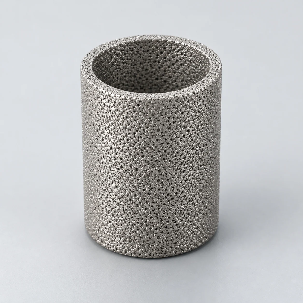
Engineering selection guidance. Confirm filtration performance, material availability and cleaning conditions for the proposed element and the actual catalyst suspension.
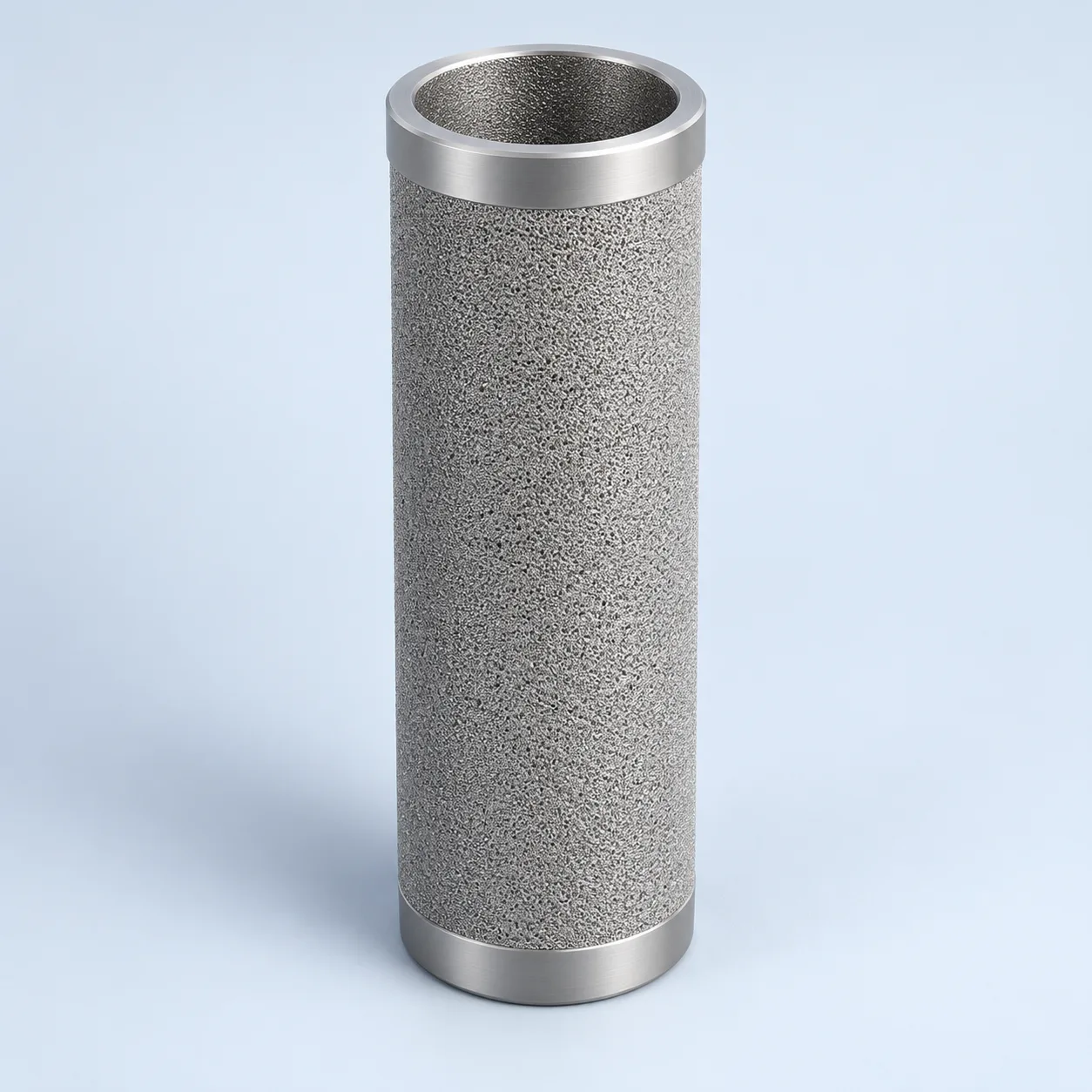
Catalyst-recovery candle — asymmetric-wall example

Catalyst-recovery candle — asymmetric-wall example. Numbered connections, filtering medium, clean passage and closure are identified.
- End connection
Connection and seals are part of the complete pressure-boundary review.
- Fine layer and porous support
The inset shows one asymmetric construction; uniform structures are separate options.
- Clarified-liquid passage
Liquid crosses the outside-in recovery wall and leaves through the bore; retained catalyst stays on the feed side.
- End closure
Closure integrity and reverse-load evidence require assembly-specific confirmation.
Batch-transfer catalyst recovery arrangement
One selected equipment arrangement is shown to explain position and flow. Verify actual flow, connections, seals and operating sequence against the equipment drawing.

- Stirred reactor / batch source
This example shows dead-end recovery during batch transfer, not a crossflow loop.
- Porous recovery candle
Outside-in filtration retains catalyst on or within the feed-side structure.
- Clarified-liquid outlet
Filtrate leaves through the bore and clean collector.
- Retained-solids recovery
A separate discharge is shown for retained catalyst; isolation and recovery procedure need design review.
Product images
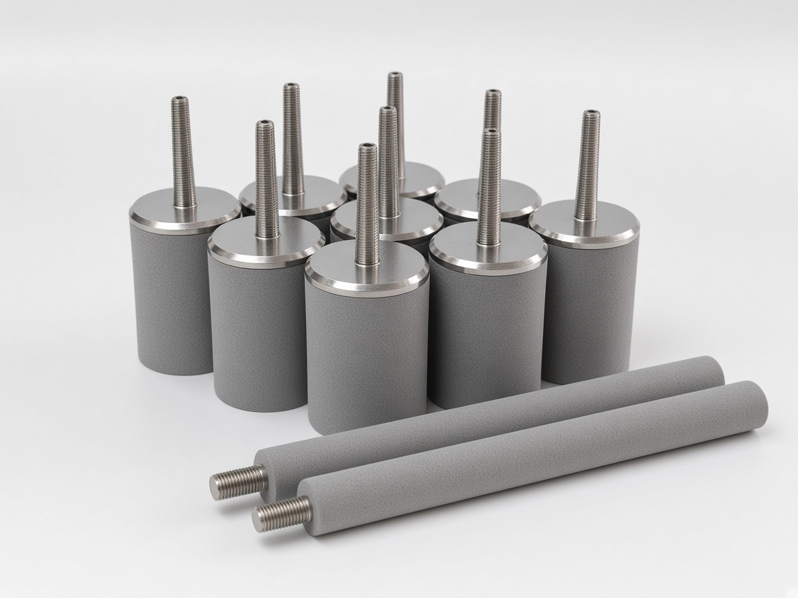
Shown arrangement: batch-transfer catalyst recovery
The installation diagram shows a dead-end filter in a batch-transfer line from a stirred reactor. Suspension enters the housing around the candles, clarified liquid leaves from the isolated clean collector, and retained catalyst has a separate controlled recovery outlet. No return to the reactor or tangential circulation is shown.
An external reactor circulation loop is a different system arrangement: define its return stream, solids discharge and pressure control on the process drawing. A crossflow module additionally requires tangential circulation along its membrane surface. These functions cannot be inferred from a porous material or a micron number.
- Define whether the objective is catalyst reuse, liquid polishing or both.
- Account for catalyst attrition: the fine tail may change during circulation.
- Confirm isolation, draining and safe solids recovery in the equipment design.
Define acceptance before choosing media
A more restrictive medium can reduce initial particle passage while also increasing pressure loss or shortening the cycle. Use a representative suspension to compare catalyst recovery, clean filtrate and regenerated permeability. Record the test conditions so a later quotation comparison uses the same basis.
On a small screen, scroll the table sideways to see every column.
| Parameter | Unit or definition | Decision | Required evidence |
|---|---|---|---|
| Catalyst population | Particle-size distribution; solids mass fraction | Choose retention target and fouling test | Representative fresh and used catalyst |
| Filtrate quality | mg/L or agreed analytical method | Set acceptance rather than assuming zero passage | Downstream process limit and sampling method |
| Liquid throughput | m³/h; viscosity at °C | Estimate area and clean resistance | Normal and end-of-batch conditions |
| Membrane construction | Fine layer, support, thickness and alloy | Compare surface and depth deposition | Actual construction and integrity method |
| Forward/reverse loading | bar and cycle count | Check loading and regeneration stresses | Element limits at process temperature |
| Recovery cycle | Duration, residual solids and rinse volume | Evaluate reusable application | Post-cleaning retention and permeability |
Asymmetric and uniform porous structures
An asymmetric structure combines a finer separation layer with a coarser support. A uniform porous body distributes its pore structure through the wall. Compare the required particle size in micrometres and retention efficiency with pressure loss, layer adhesion, catalyst abrasion and recoverable permeability. Neither construction establishes a guaranteed removal point without representative testing.
Alloy condition and fabrication
For C-276 and alloy 625, review the exact grade, product form, heat treatment and welded condition. Dense base-metal corrosion data do not qualify a porous wall, a joint or a complete element. Relate the compatibility assessment to the process mixture and cleaning exposure, then request evidence for the proposed construction.
Asymmetric layers and alloy selection
For solvent or corrosive service, compare the complete fluid chemistry with the exact alloy. A suitable 316L design can be a starting candidate; C-276, alloy 625 or titanium require a specific reason and compatible fabrication. Include trace impurities, catalyst chemistry, cleaning reagents and weld condition. A broad nickel-alloy description is incomplete as a purchase specification.
- Separate the fine-layer grade from the support and end-fitting grades.
- Check whether deposits can be released without damaging the separation layer.
- Retain unresolved compatibility questions in the technical clarification record.
Specify the regeneration trial
Reverse cleaning may use compatible liquid or gas according to the actual equipment design. Specify the allowed pressure, temperature change and discharge route; do not assume every rigid element tolerates the same reverse pulse. Request a trial that measures useful flow recovery and catalyst leakage after cleaning. Send the process diagram, chemistry, solids data, target filtrate quality and intended campaign length with the inquiry.
- A short clean-water test does not reproduce catalyst fouling.
- Report both initial performance and performance after repeated cycles.
Choose the wall structure for catalyst recovery
A uniform powder wall and a finer separation layer on a coarser support are different candidates for the shown batch-transfer filter. The second construction separates the filtration and support functions, but its benefit depends on cake release, abrasion and the stability of the bonded layer.
A model number is not a retention result. Ask for the particle size together with its measured efficiency, challenge material and test method; do not read a micron rating from the product code.
A porous plate and a porous candle can both present a rigid separation surface, but their supports and filtrate collection are different. A plate needs a supported span and an edge seal; a candle transfers filtrate through its bore and end connection. A flat-media result therefore cannot rate the installed candle or its seals.
On a small screen, scroll the table sideways to see every column.
| Choice | Why it matters | What to verify |
|---|---|---|
| Uniform or layered wall | Particle penetration and cake formation can differ. | Representative suspension; clean and regenerated permeability. |
| Selective-layer location | The layer and support see different flow and abrasion loads. | Section drawing, dirty face and permitted normal/reverse loads. |
| Joints and clean collector | A bypass path can defeat the selected medium. | End connections, seal integrity and drawing revision. |
| Recovery sequence | Releasing catalyst must not damage the wall or contaminate the next batch. | Repeated-cycle catalyst loss, filtrate quality and post-cleaning integrity. |
- Keep a circulation loop or tangential module as a separate equipment proposal; neither follows from the word membrane.
Specification and acceptance checks
For the illustrated batch-transfer arrangement, align the candle, clean-side connection and catalyst discharge with one controlled drawing. Element-specific ratings are confirmed for each project; acceptance should measure recovery and filtrate quality with representative suspension.
On a small screen, scroll the table sideways to see every column.
| Check | Specify | Acceptance record |
|---|---|---|
| Process boundary | Batch feed, filtrate outlet and solids-recovery route | Equipment drawing matching this arrangement |
| Suspension | Used-catalyst distribution, loading and viscosity | Representative feed analysis |
| Element loading | Clean/terminal loss and reverse-cleaning load at temperature | Forward/reverse limits for the assembly |
| Recovery | Filtrate target and regeneration sequence | Repeated-cycle retention and permeability results |
- Keep housing operating pressure separate from element differential pressure.
- A circulation-loop or crossflow proposal requires its own drawing and review.
Typical specifications
On a small screen, scroll the table sideways to see every column.
| Model | Grade designation | Rating at 98 %, µm | Bubble point, Pa | Air permeability, m³/(m²·h·kPa), ≥ | Porosity, % |
|---|---|---|---|---|---|
| YS-SPM-0.1 | 0.1 | 1 | 45000 | 10 | 37 |
| YS-SPM-0.5 | 0.5 | 2 | 12800 | 60 | 37 |
| YS-SPM-1 | 1 | 3.2 | 10500 | 75 | 37 |
| YS-SPM-3 | 3 | 8.3 | 6000 | 120 | 37 |
Fine separation layer on a coarser 316L support. The grade designation is not a retention rating — use the 98 % column. External-pressure (collapse) strength ≥ 3.0 MPa (reference; not a working ΔP). OD 20–140 mm; L 100–1500 mm.
Reference values only; final specifications are confirmed for each custom order.
On a small screen, scroll the table sideways to see every column.
| Material (model) | OD, mm | Length, mm | Rating range, µm | Max. media temperature (oxidizing / inert) | Max. working ΔP, MPa (reference) |
|---|---|---|---|---|---|
| 316L (YS-SP) | 10–200 | 50–1500 (longer by welding) | 0.5–65 | 400 °C / 600 °C | 0.6 |
| Titanium Gr1 (YS-TI) | 14–150 | 20–1500 | 0.22–60 | 280 °C / — | 0.6 |
| Alloy 600 (YS-NA-600) | 20–200 | 20–1500 | 5 / 10 / 20 / 40 | 800 °C / by project | 0.6 |
| Alloy 400 (YS-NA-400) | 20–200 | 20–1000 | 5 / 10 / 20 / 40 | 500 °C / 600 °C | 0.6 |
| Alloy C-276 (YS-NA-276) | 20–100 | 20–1000 | 5–40 | by project | by project |
| Bronze (YS-BR) | by design | by design | 0.5–120 | by project | by project |
Standard 316L OD: 20, 25, 30, 40, 50, 60, 70, 80, 90, 100, 140 mm. End fittings: thread, flange, socket, quick-connect, welded caps. Temperatures are limits of the porous material; assembled elements are limited by seals and joints. Working ΔP is not the same as the external-pressure (collapse) strength.
Reference values only; final specifications are confirmed for each custom order.
Prepare the specification for this application
Use these guides to resolve the next selection questions for this element. Each covers a separate part of the specification.
Product family: Sintered metal powder filter elements
- Sintered filter micron rating: what it does and does not tell you
Translate catalyst-loss and filtrate-quality limits into a defined retention test.
- Sintered metal filter pressure drop and flow area
Compare batch-transfer flow and loaded pressure drop on the same slurry basis.
- How to clean sintered metal filters safely
Specify catalyst removal and regeneration checks without assuming full flow recovery.