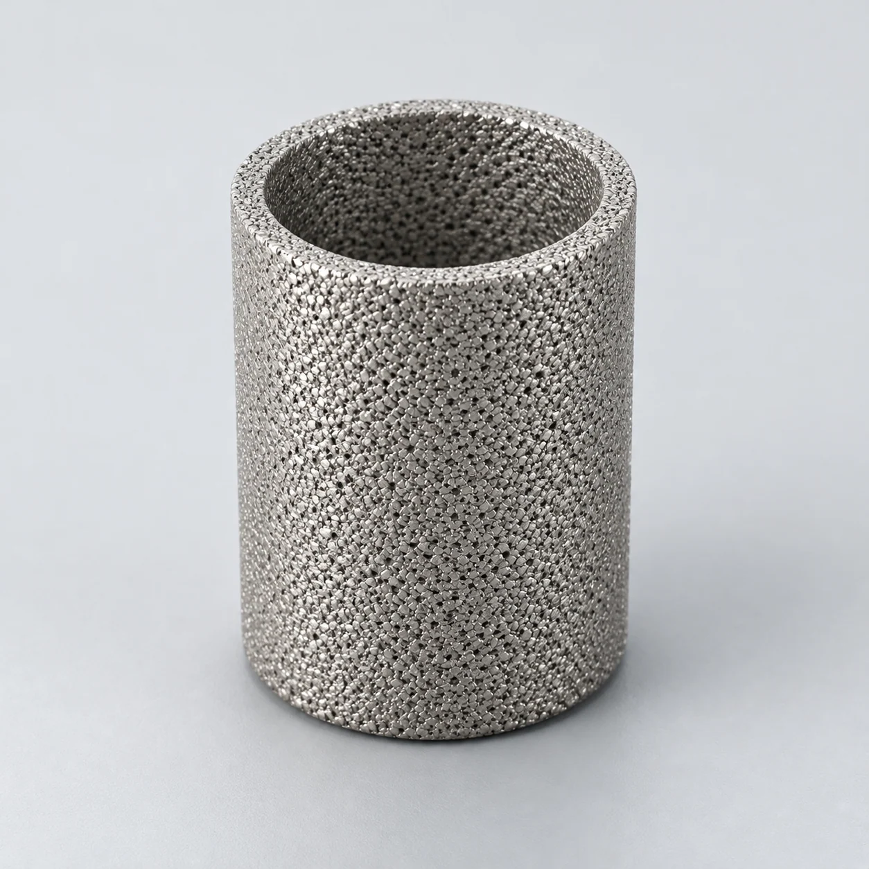

Technical guidance for refinery filtration. Outlet cleanliness, operating cycle and service life require representative process evidence and acceptance criteria for the proposed system.
Open-ended porous tube — section
- Porous tube wall
Part of the liquid crosses the wall from the bore toward the separate filtrate collector.
- Open axial passage
Both tube ends remain open so slurry and retained fines can continue to the retentate manifold.
- End seals
The seals separate dirty manifolds from the outer filtrate space; mounting details require the actual module drawing.
FCC slurry oil — selected crossflow layout
This drawing deliberately selects an inside-out crossflow module with open-ended tubes. Slurry travels along each bore; part of the liquid crosses the wall to a separate outer filtrate collector. Retentate remains in the bore and leaves through the downstream manifold for the designed recirculation or solids-handling route. It does not represent a blind-ended dead-end candle cycle.

- Feed manifold
The inlet distributes liquid slurry to the open tube bores, not to the outer filtrate chamber.
- Open-ended porous tubes
Axial slurry flow and outward permeation are different paths. Tube geometry and retention require project confirmation.
- Separate filtrate collector
Liquid crossing the porous walls enters the outer collection space and leaves through its own outlet.
- Retentate manifold and seals
End seals isolate the filtrate chamber. Retentate continues to the specified recirculation or solids-handling system.
Slurry-oil filter vessel, not regenerator flue-gas filter
FCC slurry-oil filtration treats a liquid stream containing catalyst fines. It is a different process from removing dust from regenerator flue gas; the two applications must not share one element selection simply because both originate in an FCC unit. Show the liquid feed, filtrate outlet, retentate or solids discharge and recirculation path on the process diagram.
A designed crossflow module may pass slurry along the inside of open-ended porous tubes, with filtrate crossing to an outer collector and concentrated slurry returning or leaving through the retentate line. A dead-end candle arrangement instead accumulates solids until its designed discharge cycle. The correct geometry follows the chosen system, acceptable residual oil and solids-removal strategy.
- Check whether the requested replacement is a blind-ended candle or open-ended membrane tube.
- Treat viscosity and fouling tendency at operating temperature as essential inputs.
- Identify abrasive solids and potential deposits, not only total particle concentration.
Compare proposed elements on the same process basis
A nominal micron rating does not predict final catalyst concentration in a fouling slurry. An application trial should measure filtrate quality, sustainable flux, cleaning recovery and oil loss. Normalize those measurements before comparing proposed materials or element dimensions.
On a small screen, scroll the table sideways to see every column.
| Parameter | Unit or definition | Decision | Required information |
|---|---|---|---|
| Feed solids | mg/kg or mass fraction; particle distribution | Define retention and erosion application | Representative slurry analysis and variation |
| Filtrate target | Agreed concentration and analytical method | Set acceptance for downstream use | Sampling, repeatability and acceptance limit |
| Viscosity and temperature | mPa·s at °C | Set hydraulic and deposition conditions | Normal, upset and cooldown data |
| Flux and recirculation | Filtrate m³/(m²·h); loop m³/h | Compare sustainable operation | Effective area, circulation basis and solids balance |
| Differential pressure | Forward/reverse bar at temperature | Check loading and cleaning stresses | Control setpoints and proposed element limits |
| Construction | Alloy, wall/layer, ends and seals | Fit system and cleaning method | Drawing, traceability and inspection plan |
Slurry filtration and crossflow arrangement
Liquid FCC slurry-oil filtration separates catalyst fines from a hydrocarbon stream; it is a different application from regenerator flue-gas filtration. In an inside-out crossflow layout, feed moves along the open element channel, filtrate crosses the porous wall and a concentrated stream leaves the channel. Confirm the recirculation, concentrate discharge and regeneration sequence from the process design.
Material and assembly qualification
A material grade suitable for one refinery stream may be unsuitable for another. Review sulfur-bearing species, chlorides, temperature and cleaning exposure against the exact porous material, welds and fittings. Dense-alloy data are an input to this review; filtration performance and complete-assembly qualification need separate evidence.
Choose an alloy for the actual slurry
A porous stainless body or an asymmetric metal membrane may be a candidate, but the feed's chemical and thermal history must justify the material. Record water, sulfur species, chlorides and any cleaning or decoking reagents. High alloy content does not remove the need to evaluate deposits, corrosion beneath them, abrasion or fabrication quality.
If nickel alloys are proposed, specify the actual grade, separating layer, support and end fittings. C-276 and alloy 625 solve different combinations of conditions; neither should be selected solely from a generic corrosion-resistant label. Material handbooks describe alloy behavior, not a complete cartridge's filtration or cyclic life.
- Verify joints and flow channels against the approved module drawing.
- Keep initial clean pressure loss separate from sustainable fouled operation.
- Retain unknown source properties as questions in the inquiry.
Define regeneration and inspection together
A reverse cycle or circulation sweep can be part of a designed regeneration sequence, but its pressure, fluid and temperature must be compatible with the element and process. Test recovery with representative aged slurry where practical; a short clean-fluid test cannot establish fouling resistance. Submit the process diagram, solids/viscosity analyses, target filtrate quality, cleaning method and existing module drawing. Record the required checks after a cleaning campaign before reusing an element.
- Do not promise outlet solids from an unrelated refinery case.
- Keep filter and vessel pressure limits explicit in the technical specification.
Match an asymmetric wall to the crossflow channel
For the illustrated open-ended crossflow tube, require a channel-section drawing before comparing uniform and asymmetric walls. Retain the shown inside-out filtration path: slurry circulates along the bore, filtrate crosses the porous wall to the outer collector. Confirm whether the fine-pore separation layer is inside or outside, and trace the separate cleaning path on that drawing. A layer on the opposite face is a different configuration, not an interchangeable micron rating.
Use representative aged slurry to test the proposed wall. A clean-water curve or a general catalyst-filtration application does not establish FCC flux, catalyst-fines removal or oil loss.
On a small screen, scroll the table sideways to see every column.
| Interface | Required input | Trial observation |
|---|---|---|
| Open channel | Bore, length, inlet/outlet connections and circulation conditions. | Channel pressure loss and deposit distribution. |
| Porous wall | Layer location, wall thickness, active area and temperature. | Filtrate flux and catalyst passage at the agreed trans-wall pressure difference. |
| Regeneration | Chosen sweep or reverse cycle, fluid and solids-discharge route. | Recovered permeability and layer/joint integrity. |
| Oil and solids balance | Circulation, filtrate and concentrate measured separately. | Filtrate solids, retained catalyst and oil carried out with the solids. |
- The normal crossflow circulation is not itself a backwash cycle; retain the separate regeneration definition.
Specification and acceptance checks
Specify the shown open-ended crossflow tube and its connections without converting it to a closed-end candle. Element-specific ratings are confirmed for each project; acceptance must distinguish filtrate flux from circulation flow and measure catalyst removal under representative slurry conditions.
On a small screen, scroll the table sideways to see every column.
| Check | Specify | Acceptance record |
|---|---|---|
| Geometry | Tube ends, seals, collectors and circulation path | Controlled crossflow assembly drawing |
| Slurry | Catalyst loading, particle distribution and viscosity at temperature | Representative feed and analysis method |
| Hydraulics | Filtrate flux, circulation and forward/reverse differential pressure | Common area and temperature basis |
| Cycle result | Filtrate solids, cleaning recovery and oil loss | Repeated-cycle trial and inspection |
- Separate line pressure, trans-wall differential pressure and cleaning supply pressure.
- Agree the cleaning discharge route and solids balance before trial.
Typical specifications
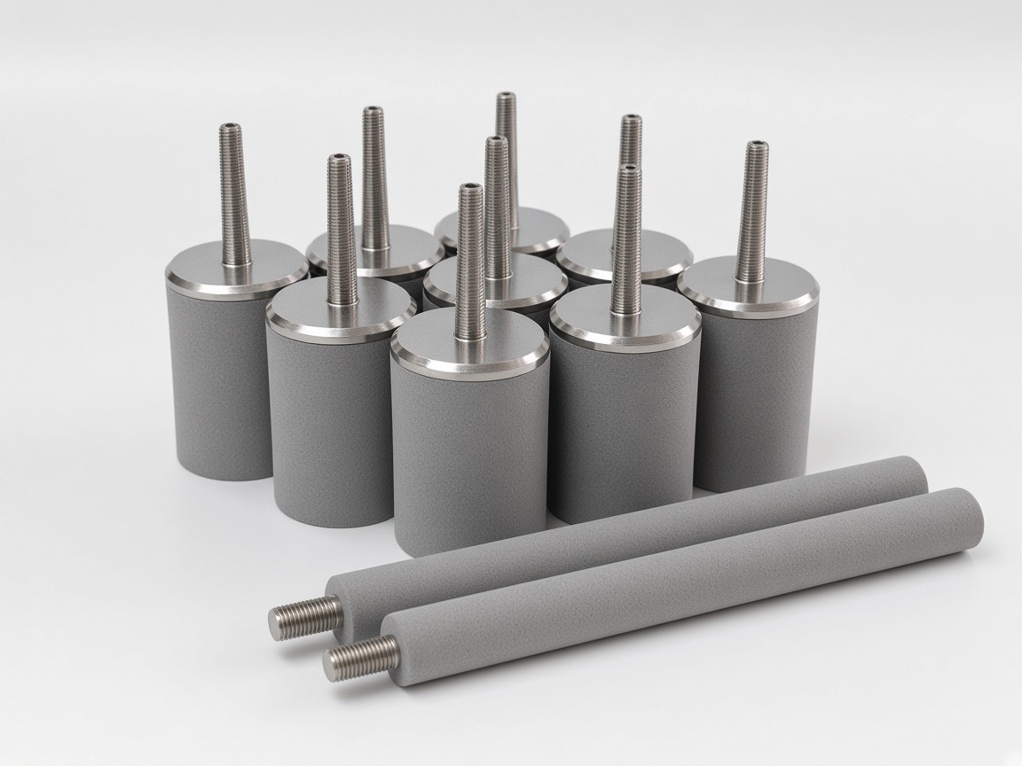
Powder-media form; the open-ended crossflow configuration above requires its own end connection and flow-through geometry.
On a small screen, scroll the table sideways to see every column.
| Material (model) | OD, mm | Length, mm | Rating range, µm | Max. media temperature (oxidizing / inert) | Max. working ΔP, MPa (reference) |
|---|---|---|---|---|---|
| 316L (YS-SP) | 10–200 | 50–1500 (longer by welding) | 0.5–65 | 400 °C / 600 °C | 0.6 |
| Alloy 600 (YS-NA-600) | 20–200 | 20–1500 | 5 / 10 / 20 / 40 | 800 °C / by project | 0.6 |
Standard 316L OD: 20, 25, 30, 40, 50, 60, 70, 80, 90, 100, 140 mm. End fittings: thread, flange, socket, quick-connect, welded caps. Temperatures are limits of the porous material; assembled elements are limited by seals and joints. Working ΔP is not the same as the external-pressure (collapse) strength.
Reference values only; final specifications are confirmed for each custom order.
Prepare the specification for this application
Use these guides to resolve the next selection questions for this element. Each covers a separate part of the specification.
Product family: Sintered metal powder filter elements
- Sintered filter micron rating: what it does and does not tell you
Define the catalyst-fines target and sampling basis for filtrate acceptance.
- Sintered metal filter pressure drop and flow area
Use the pressure-budget and active-area checklist, keeping circulation and filtrate flow as separate inputs.
- How to clean sintered metal filters safely
Define regeneration and inspection using representative slurry and deposits.